Before removing any sensor or engine control unit, you need to disconnect the negative terminal of the battery.
Removing the controller
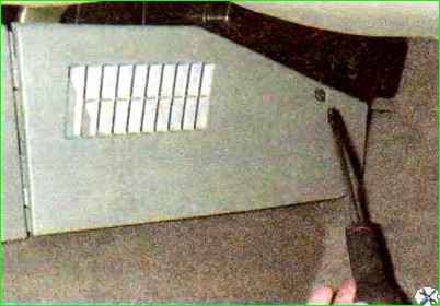
Remove the right side lining of the floor tunnel.
Use a Phillips screwdriver to unscrew the screw fastening the right side trim and, moving it forward, remove it.
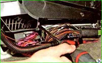
Use a Phillips screwdriver to unscrew the self-tapping screw securing the rear controller bracket to the heater body.
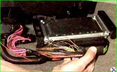
Remove the controller from the guides of the heater housing.
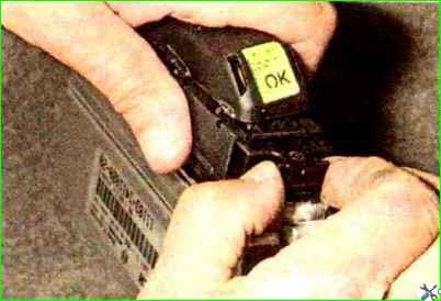
Pull out the lock of the engine control system wiring harness
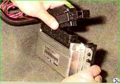
Remove the engine control system wiring harness block.
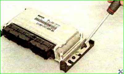
Use a Phillips screwdriver to unscrew the screw securing the controller bracket
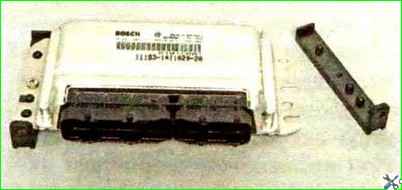
Remove the bracket. Similarly, remove the other bracket.
Install the controller in reverse order.
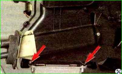
During installation, we insert the controller brackets into the guides of the heater housing (for clarity, shown on a removed heater)
Removing the crankshaft position sensor
Checking the crankshaft position sensor is shown in the article “diagnosis of faults.”
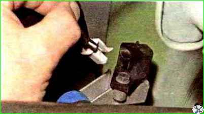
With the ignition off, release the lock of the engine management system wiring harness block and disconnect the wiring harness block from the crankshaft position sensor.
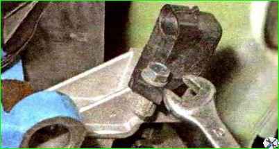
Use a 10mm wrench to unscrew the sensor mounting bolt
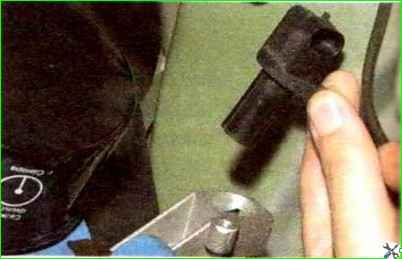
Remove the sensor from the hole in the boss on the oil pump body
Install the crankshaft position sensor in reverse order
Removing the phase sensor
Checking the phase sensor is shown in the article “How to check the phase sensor of a Lada Kalina car.”
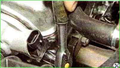
Press the clamp of the engine control system wiring harness block and disconnect the block from the phase sensor
Use a 10mm socket to unscrew the sensor mounting bolt
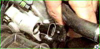
Remove the sensor from the hole in the cylinder head plug
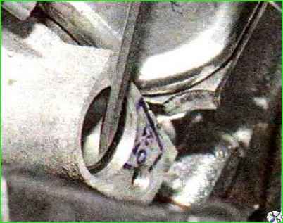
The connection between the phase sensor and the cylinder head plug is sealed with a rubber ring.
Use a screwdriver to pry off the rubber ring
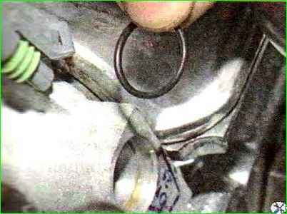
Remove the ring from the groove of the plug. If the ring is damaged, replace it. Having installed the ring, lubricate it with engine oil
Installing the phase sensor in reverse order
Replacing the coolant temperature sensor
Checking the sensor is described in the article “How to check the coolant sensor on Lada Kalina.”
We carry out the work on a cold engine.
For convenience, remove the cover of the air filter housing with the mass air flow sensor and the air supply hose to the throttle assembly.
Partially drain the coolant.
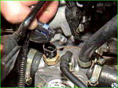
Press the clamp of the engine management system wiring harness connector and disconnect the wiring harness block from the coolant temperature sensor
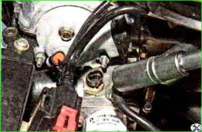
Use a high 19mm socket with an extension to unscrew the sensor
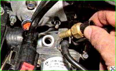
Remove the sensor from the hole in the exhaust pipe of the cooling system
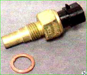
The sensor connection is sealed with a copper washer.
Install the sensor in reverse order. Add liquid to normal level.
Replacing the throttle position sensor
Checking the sensor is described in the article “How to check the sensor and circuit of the Lada Kalina throttle position sensor.”
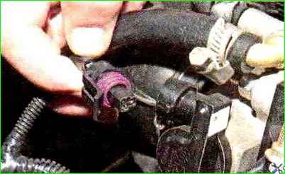
Press the connector lock of the engine management system wiring harness and disconnect the block from the throttle position sensor.
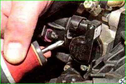
Use a Phillips screwdriver to unscrew the two sensor mounting screws.
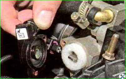
Remove the sensor from the throttle assembly
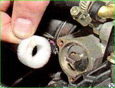
Remove the sealing foam ring
Before installing the sensor, make sure that the throttle valve is completely closed.
Install the sensor on the throttle assembly so that the shank of the damper axis fits into the groove of the sensor.
Fix the sensor with screws and connect the wiring harness block to it.
Removing the mass air flow sensor
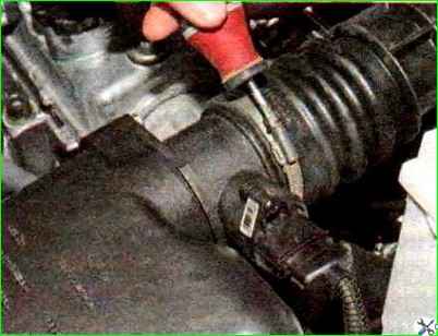
Use a Phillips screwdriver to loosen the clamp of the air supply hose to the throttle body
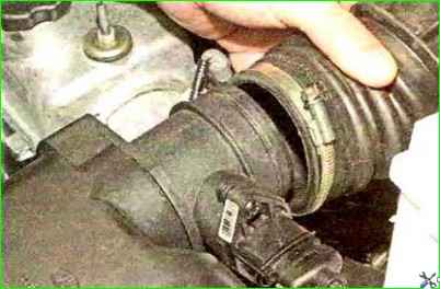
Remove the hose from the mass air flow sensor (MAF) pipe.
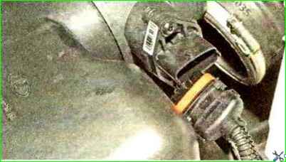
Press the block retainer (the clamp is located at the bottom of the block) of the SUD wiring harness and disconnect the harness block wires from the sensor
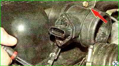
Using a 10mm socket with an extension, unscrew the two bolts securing the mass air flow sensor to the air filter housing cover
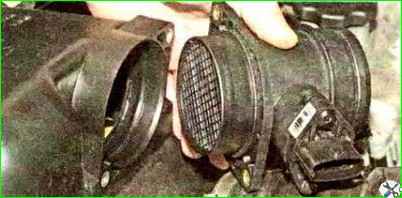
Remove the sensor
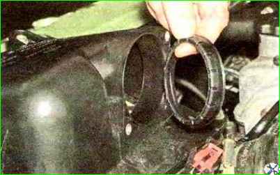
Remove the sealing sleeve of the sensor.
Before installing the sensor, we put the sealing sleeve on it until it stops. Further installation of the mass air flow sensor is carried out in the reverse order.
Replacing the knock sensor
Checking the sensor is described in the article “Checking and replacing the knock sensor.”
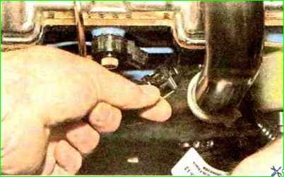
Press the wire clamp of the ECM wiring harness block and disconnect the wiring harness block from the knock sensor (for clarity, the high-voltage wires of the 2nd and 3rd cylinders have been removed, the throttle drive cable is moved to the side).
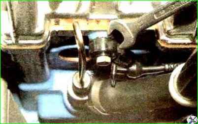
Use a 13mm wrench to unscrew the sensor mounting bolt
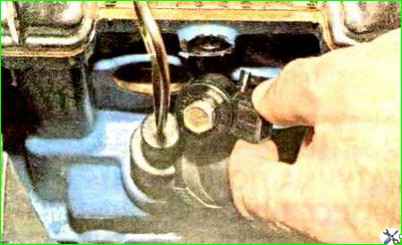
Remove the sensor and remove the bolt
Before installing the sensor, clean the surface of the cylinder block at the location where the sensor is installed. Install the sensor in reverse order
Replacing the control oxygen concentration sensor
For clarity, shown with the receiver removed.
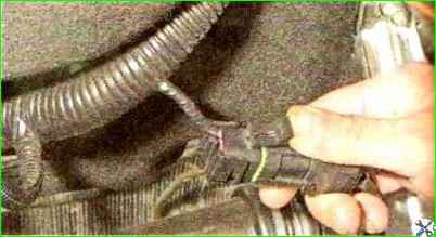
Press the clamp of the wire block
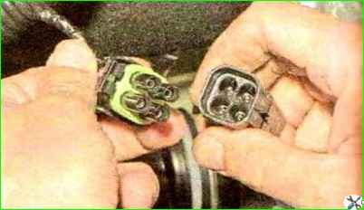
Disconnect the wiring harness block
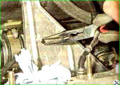
Squeezing the tendrils of the oxygen concentration sensor wiring harness holder with pliers, remove the harness from the heat shield of the steering mechanism
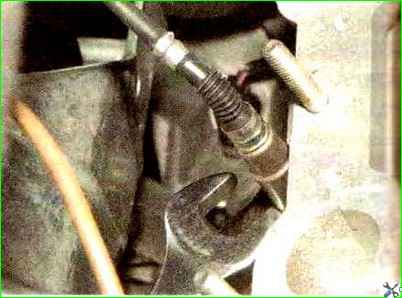
Use a 22mm wrench to unscrew the sensor from the hole in the catalytic collector
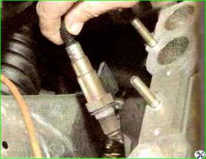
Remove the control oxygen concentration sensor
Before installing the sensor, apply graphite lubricant to its threads.
Replacing the speed sensor
Checking the speed sensor is described in the article “Checking and replacing the speed sensor.”
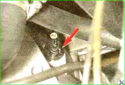
Press the pad lock and disconnect the pad from the speed sensor.
Further operations are shown on the removed gearbox
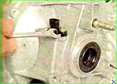
Use a 10mm wrench to unscrew the nut securing the speed sensor
Remove the sensor from the hole in the clutch housing
In prot A sealing rubber ring is installed on the sensor rod
Removing the ignition coil (module)
Checking the coil is described in the article “Checking the serviceability of the Lada Kalina ignition module.”
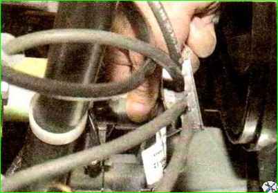
Remove the wire ends from the coil.
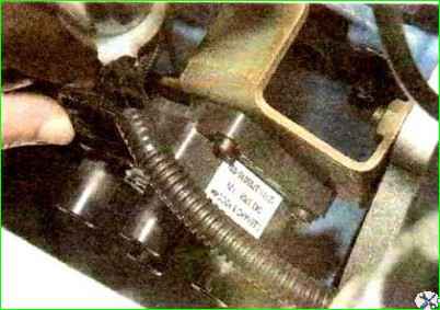
Pressing the lock of the wiring harness block, disconnect the block from the coil.
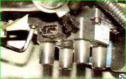
Use a 5mm hex to unscrew the four screws securing the coil to the bracket and remove the ignition coil.
Install in reverse order.
The numbers of the cylinders to which the high-voltage wires must be connected are marked on the coil body.
Replacing the immobilizer control unit
Remove the instrument panel trim.
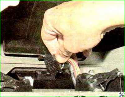
Disconnect the SUD wiring harness block from the immobilizer control unit
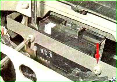
Use a Phillips screwdriver to unscrew the screw securing the block, holding the screw nut from turning with a 10mm wrench. We also unscrew the second screw.
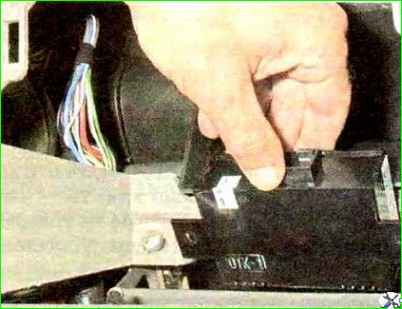
Remove the immobilizer control unit from the instrument panel socket.
Install the immobilizer control unit in reverse order.
If the control unit fails, you must use a clean, untrained unit
To restore the functionality of the anti-theft system, it is necessary to carry out the procedure for training it using an existing training key.


