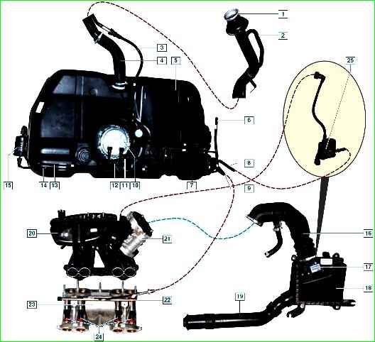
The power system consists of a fuel tank, a fuel module, a fuel filter, a fuel rail with injectors, an air filter, fuel lines, air ducts, a throttle assembly, an intake pipe, and a gasoline vapor recovery system
The air entering the engine cylinders is cleaned of dust by an air filter.
The air filter is installed in the engine compartment on three rubber supports.
The filter element is replaceable, made of special paper.
To prevent contaminated air from leaking into the intake tract, there is a sealing edging at the top of the element.
To replace the filter element, the filter cover is removable.
The purified air passes through the mass air flow sensor through the air duct to the throttle valve.
The electric throttle valve regulates the amount of air entering the engine cylinders.
The damper rotates on an axis in the housing (pipe).
The throttle body is secured to the intake manifold flange with four bolts.
The fuel supply is stored in a tank with a capacity of 50 liters.
The fuel tank is made of special plastic and is suspended from the bottom of the car on two steel clamps.
The filler neck of the fuel tank is located on the right side of the car and is closed with a plug.
Fuel from the tank is supplied by an electric submersible fuel pump.
The pump is installed in the fuel tank. To access the pump, there is a hatch with a cover in the bottom of the car under the rear seat cushion.
A mesh filter is installed on the inlet pipe of the fuel pump, which traps small solid particles of debris that have entered the fuel tank along with gasoline.
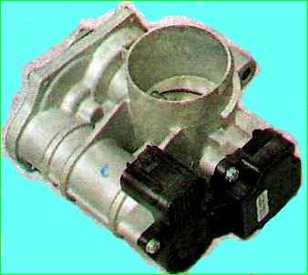
The throttle body, with a position sensor and an electric damper drive installed on it, form a throttle unit.
The pump is supplied with voltage at the command of the ECU when the ignition is turned on.
If no attempt is made to start the engine, then after 2-3 seconds the ECU will turn off the fuel pump.
The fuel pump is combined with a fuel level sensor and a fuel pressure regulator into a single unit - a fuel module (often called an electric fuel pump).
Fuel from the pump (through the outlet pipe of the fuel module) enters the fuel filter.
Purified gasoline is again supplied through the fuel line and through a tee to the inlet pipe of the fuel module and then supplied to the fuel rail.
Excess fuel is released through the pressure regulator into the tank.
The fuel pressure regulator is installed in the fuel module cover.
The fuel pressure regulator is a bypass valve that maintains in the system (fuel line) a working pressure of 378-390 kPa, necessary for the proper operation of the injection system.
The fuel filter is made of paper, installed in a non-separable metal housing.
Purified fuel flows through the fuel line into the fuel rail.
The fuel rail holds four injectors and supplies fuel to them.
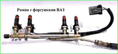
The connection between the ramp and the injectors is sealed with rubber rings.
The ramp is bolted to the intake manifold.
In accordance with current environmental requirements, the vehicle is equipped with a fuel vapor recovery system; the above-fuel space of the tank is connected to the atmosphere not directly, but through the elements of this system.
The system consists of an adsorber, an adsorber purge valve, connecting tubes and hoses.
Gasoline vapor through pipes and with connecting hoses enter the adsorber, which prevents vapors from entering the atmosphere.
An adsorber is a container where gasoline vapors are absorbed by activated carbon.
When the engine is running at high crankshaft speed, the ECU sends a signal to open the canister purge valve, and gasoline vapors are sucked into the intake manifold receiver.
The adsorber is mounted on the fuel tank on the front left side and covered with a protective screen.
Air is supplied to the intake valves of the engine cylinders through the receiver and the intake manifold.
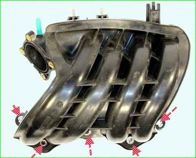
The engine receiver is made of special plastic.
The filler plug has two valves: one for emergency release of fuel vapor pressure from the tank (which is possible when the ambient temperature rises), and the other for the entry of air from the atmosphere when fuel is consumed from the tank (this eliminates the occurrence of strong vacuum in the tank ).
- Fuel (according to GOST R51105-97) - Premium-95 or Premium Euro-95 gasoline
- Fuel tank capacity 50 l
- Fuel module 1118-1139008-20
- Fuel rail 1118-1144010,1118-1144010-01
- Operating fuel pressure in the fuel rail 378-390 (3.8-3.9) kPa (bar)
- Fuel injectors 1118-1132010/-01
- Air filter element 2112-1109080
- Inlet module (receiver) 21116-1008600
- Throttle assembly 21116-1148010
")

")
")
")
")
")
")
")