The engine cooling system on the Lada Granta is liquid, forced cooling
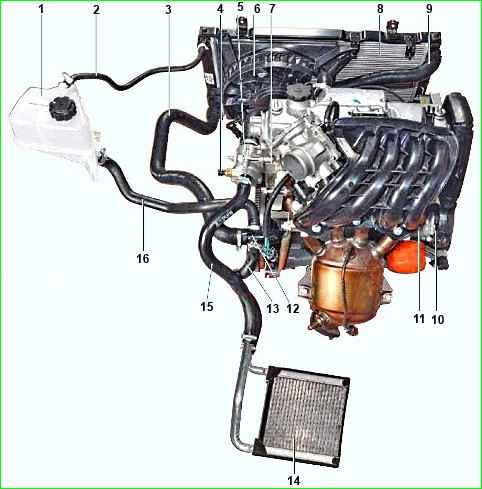
Cooling system: 1 - expansion tank; 2 - steam removal hose of the radiator of the cooling system; 3 - outlet hose of the radiator of the cooling system; 4 - coolant temperature sensor; 5 - thermostat housing; 6 - fan; 7 - cylinder head; 8 - radiator of the cooling system; 9 - supply hose to the radiator of the cooling system; 10 - coolant pump; 11 - cylinder block; 12 - pump supply pipe; 13 - heater radiator outlet hose; 14 - heater radiator; 15 - heater radiator supply hose; 16 - inlet hose
Consists of an expansion tank, a coolant pump, cooling jackets for the cylinder head and cylinder block, a thermostat, a radiator with an electric fan, connecting hoses and a pump supply pipe.
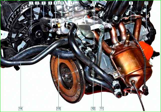
Cooling system elements: 1 - fan; 2 - radiator of the cooling system; 3 - supply hose to the radiator of the cooling system; 4 - thermostat housing; 5 - coolant temperature sensor; 6 - thermostat cover; 7 cylinder head; 8 - pump supply pipe; 9 - cylinder block; 10 - coolant pump; 11 - heater radiator outlet hose; 12 - heater radiator supply hose; 13 - radiator outlet hose of the cooling system; 14 - inlet hose
The heater radiator is connected to the cooling system.
The system is filled with coolant through the filler neck of the expansion tank.
The expansion tank is mounted in the engine compartment next to the left shock absorber cup.
The tank is made of translucent plastic, which allows you to visually monitor the level of coolant in the tank.
The reservoir serves to maintain a constant level of coolant in the cooling system.
When heated, the liquid in the cooling system expands, and part of it is forced into the expansion tank.
As the engine cools, fluid from the reservoir flows into the cooling system.
The tightness of the cooling system is ensured by the inlet and outlet valves in the expansion tank plug.
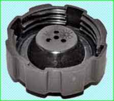
The exhaust valve maintains increased (1.1 bar) pressure in the system when the engine is hot.
Due to this, the boiling point of the liquid increases and steam losses are reduced.
The intake valve opens when the pressure in the system decreases relative to atmospheric pressure (by 0.03–0.13 bar) as the engine cools.
If the filler plug is lost, do not replace it with a sealed plug without valves.
The circulation of fluid in the cooling system is provided by a centrifugal-type vane pump, the impeller of which is driven by a timing belt from the crankshaft pulley.
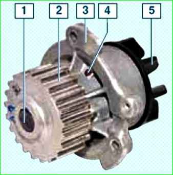
Coolant pump: 1- pump roller; 2 - toothed pulley; 3 - pump housing; 4 - control hole; 5 - impeller
The pump is attached to the cylinder block on the right.
The pump housing contains a roller that rotates in a closed bearing that does not require replenishment of lubricant.
A toothed pulley and impeller are pressed onto the ends of the roller.
The seal of the roller is ensured by the pump seal.
The pump housing has a control hole to detect fluid leakage when the pump seal fails.
If a fluid leak is detected, replace the pump assembly.
The pump pumps coolant through the cooling jackets of the engine block and cylinder head.
Next, the liquid enters the thermostat housing, mounted on the left end of the cylinder head
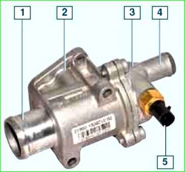
Thermostat housing assembly: 1 - pipe for connection to the supply hose of the radiator of the cooling system; 2 - body; 3 - cover; 4 - pipe for connecting to the supply hose rad heater ionator; 5 - coolant temperature sensor
A thermostat is installed in the housing, which accelerates engine warm-up, automatically maintains its thermal conditions within specified limits and regulates the amount of liquid passing through the radiator.
The thermostat housing pipe is connected by a hose to the upper pipe of the radiator of the cooling system, and the thermostat cover pipe is connected to the upper pipe of the heater radiator.
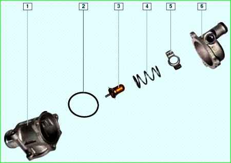
Thermostat elements: 1 - housing; 2 - sealing ring; 3 cylinder; 4 - spring; 5 - fixing plate; 6 - cover
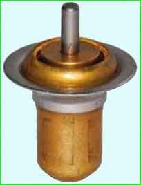
The thermostat consists of a metal cylinder with a heat-sensitive filler, a spring and its fixing plate.
The cylinder rod fits into the socket of the thermostat housing.
In the closed position of the thermostat (on a cold engine), its spring, resting on the fixing plate, presses the cylinder plate to the seat of the hole in the housing, closing the channel between the housing and the thermostat cover.
As a result, the flow of coolant through the radiator of the cooling system is blocked.
In this case, all the liquid circulates through a small circle of the cooling system: pump, cooling jackets of the cylinder block and cylinder head, thermostat housing and cover, heater radiator, steam exhaust hose of the cooling system radiator, expansion tank, pump supply pipe.
When the coolant temperature reaches (85±2) °C, the thermostat bottle filler begins to melt and increases its volume, pushing the rod out of the thermostat bottle.
At the same time, the cylinder plate moves away from the seat, and the liquid begins to circulate in a large circle, which includes the pump, cooling jackets of the cylinder block and cylinder head, thermostat housing and cover, radiator of the cooling system, steam removal hose of the radiator of the cooling system, expansion tank, heater radiator, pump supply pipe.
When the coolant reaches a temperature of (100±2) °C, the thermostat valve opens completely.
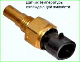
The coolant temperature sensor installed in the thermostat cover provides information to the engine control system controller.
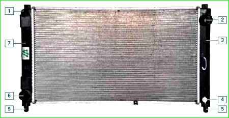
Cooling system radiator: 1 - steam exhaust hose fitting; 2 - supply hose pipe; 3 - right tank; 4 - drain plug; 5 - lower radiator mounting cushion; 6 - outlet hose pipe; 7 - left tank
The radiator of the cooling system consists of two vertically located plastic tanks connected by aluminum tubes (arranged in one row) with cooling plates.
The fluid enters the radiator through the upper pipe of the right tank, and is discharged from the radiator through the lower pipe of the left tank.
On top of the left radiator tank there is a fitting for the steam exhaust hose.
At the bottom of the right tank there is a drain hole closed with a plug.
A plastic casing with an electric fan is attached to the radiator.
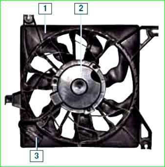
Fan with casing assembly: 1 - fan casing; 2 - fan impeller with electric motor; 3 - wire block
The fan is designed to blow the radiator when there is no or insufficient oncoming air flow to maintain normal thermal conditions of the engine.
The fan is turned on via a relay based on a signal from the engine control system controller
The fan is switched on using relay K1 at the command of the electronic unit, which evaluates the temperature using a temperature sensor installed on the thermostat body.
Thermostat opening temperature – 85 – 89°C;
Temperature of full opening of the thermostat – 102°C;
The volume of liquid in the cooling system is 7.5 l.
Possible malfunctions of the cooling system and methods of correction
- Malfunction
Diagnostics
Elimination
The engine is overheating (the overheating indicator lights up red):
- Coolant temperature sensor is faulty
Check the sensor with a tester
Replace the faulty sensor
- Thermostat is faulty
Check the thermostat
Replace the faulty thermostat
- Insufficient amount of coolant
The fluid level is below the MIN mark on the expansion tank
Fix leaks.
Add coolant
- A lot of scale in the cooling system
Flush the cooling system with descaling agent.
Do not use hard water in the cooling system.
Dilute concentrated antifreeze only with distilled water
- Radiator cells are dirty
Inspection
Rinse the radiator with a jet of water under pressure
- Coolant pump is faulty
Remove the pump and inspect the unit
Replace the pump assembly
- Cooling system electric fan does not turn on
Check the electric fan circuits
Restore contact in electrical circuits. Faulty fuse, relay, electric motor, temperature sensor, controller - replace
- Unacceptably low octane number of gasoline
Fuel your car with fuel recommended by the manufacturer
- A lot of carbon deposits in the combustion chamber, on the piston heads, valve plates
Inspection after removing the engine cylinder head
Eliminate the cause of carbon formation.
Use oil of the recommended viscosity and, if possible, low ash content
- Breakthrough of exhaust gases into the cooling system through a damaged cylinder head gasket
There is a smell of exhaust gases and bubbles appear in the expansion tank
Replace the cylinder head gasket.
Check the cylinder head for flatness
The electric fan of the engine cooling system is constantly running (even on a cold engine):
- Open circuit in the coolant temperature sensor or its circuit. The indicator light is on.
The sensor and circuits are checked with an ohmmeter
Replace the faulty sensor
- Electric fan relay contacts do not open
Checking with a tester
Replace the faulty relay
- The controller or its circuits are faulty
Check the controller or replace it with a known good one
Replace the faulty controller
The engine takes a long time to warm up to operating temperature:
- Thermostat is faulty
Check the thermostat
Replace the faulty thermostat
- Low air temperature (below –15 °C)
Insulate the engine: install shields in front of the radiator, but do not cover more than half of its area
Drop in coolant level in the expansion tank:
- Damage to the radiator, expansion tank, hoses, loosening of their fit on the pipes
Inspection. The tightness of radiators (engine and heater) is checked in a bath of water with compressed air under a pressure of 1 bar
Replace damaged parts
- Liquid leakage through the coolant pump seal
Inspection
Replace the pump
- The cylinder head gasket is damaged.
Defective block or cylinder head
On the oil level indicator there is an emulsion with a whitish tint. Possible white smoke may appear from the muffler and oil stains on the surface of the coolant (in the expansion tank).
Coolant leaks on the outer surface of the engine
Replace damaged parts.
Do not use water in the cooling system; fill in coolant appropriate to the climatic conditions
")

")
")
")
")
")
")
")