The car has a rear axle with a continuous beam
The beam consists of a cast iron crankcase 15 with axle housings pressed into it, into which axle shafts 13 of the semi-balanced type are inserted
The flanges of the axle housings have slots where the bearings of 2 axle shafts are located.
The brake shields of the rear brakes with brake mechanisms are attached to the flanges of the axle housings.
A breather 14 is installed in the upper part of the left axle casing to prevent the creation of excess pressure in the crankcase cavity.
There is a hatch on the rear side of the crankcase through which the main gear units are mounted.
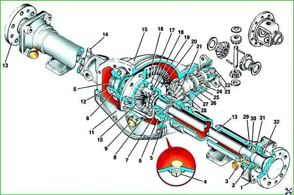
Rear axle GAZ-3110:1 - outer oil seal housing; 2 - axle bearing; 3 - oiler: 4 - oil drain plug; 5 - differential bearing adjusting nut; 6 - bearing cover; 7 - differential bearing; 8 - support washer; 9 - oil filler plug; 10 - semi-axial gear; 11 - crankcase cover; 12 - locking plate; 13 - axle shaft; 14 - breather; 15 - rear axle housing; 16 - driven gear; 17 - satellite axis; 18 - satellite; 19 - support washer; 20 - differential box; 21 - drive gear; 22 - nut; 23 - drive gear flange; 24 - oil seal; 25 - front drive gear bearing; 26 - spacer ring; 27 - rear bearing of the drive gear; 28 - adjusting ring; 29 - axle shaft seal; 30 - locking sleeve; 31 - spring ring; 32 - outer oil seal packing
The main gear is hypoid, with a gear ratio i = 3.9. The hatch is closed from the outside with a stamped cover 11.
Sealing of the crankcase and cover is ensured by a paronite gasket installed between them.
There is an oil filler plug 9 in the cover, and an oil drain plug 4 is installed in the lower part of the crankcase.
The drive gear shaft 21 is mounted in the front part of the crankcase on two tapered roller bearings.
The front part of the shaft is splined; the flange 23 of the drive gear is installed on it from the outside.
For tightness, an oil seal 24 is installed in the front part of the crankcase.
Between the rear bearing 27 and the end of the drive gear there is an adjusting ring 28, which provides the required mounting size to compensate for errors in the processing of the drive and driven gears to achieve the optimal depth of engagement of the teeth of the main gear gears.
Between the front bearing 25 and the shoulder of the drive gear shaft, spacer rings 26 are installed, the selection of the thickness of which ensures the necessary preload of the drive gear bearings.
Bearing preload is achieved by tightening the castle nut on the threaded end of the drive gear shaft to a certain torque and is checked by the amount of rotation force of the drive gear flange.
Castle nut 22 is locked with a cotter pin.
This design uses a gear-type differential.
Differential box 20 is one-piece. The driven gear 16 is attached to it with bolts and nuts.
The heads of the fastening bolts have an eccentric shape relative to the threaded part.
In the body of the driven gear there are holes with recesses of a similar shape.
When installing the driven gear, the bolts are installed so that their heads fit completely into the recesses.
This installation allows you to secure the bolts from turning when installing (dismantling) the driven gear to the differential box.
In the differential box 20 there are two semi-axial gears 10 and two satellites 18, which are in constant mesh.
Between the differential box, the ends of the gears and satellites, support washers 8 and 19 are installed.
The satellites rotate around axis 17, fixed in the differential box with a stopper.
Tapered roller bearings 7 are pressed onto the axles of the differential box.
The beam housing has mounting sockets for installing a differential and threaded adjusting nuts for 5 differential bearings.
The differential assembly with the driven gear and bearings is attached to the beam housing with two covers using bolts.
At the factory, the seats in the crankcase and 6 bearing caps are machined together, so the 6 caps are not interchangeable.
Adjusting nuts 5 ensure the required lateral clearance between the main gear gears and the preload of the differential box bearings.
The adjusting nuts are secured against movement by locking plates 12, which are attached to the covers with bolts.
The axle shaft is splined into the axle gear. The outer part of the axle shaft, through ball bearing 2, rests on the bearing seat located in the flange of the axle shaft casing.
To add lubricant to the bearing, there is a grease cap 3 installed on the axle shaft flange.
Socket bearing Nika has a drainage slot for draining transmission oil, which prevents leaked oil from entering the brake mechanism parts.
A spring ring 31 is installed between the outer ring of the bearing and the end of the bearing seat.
The bearing is secured against axial movement by a locking sleeve 30, which is pressed onto the axle shaft in a heated state.
Inside the axle housing there is a socket into which the rubber oil seal 29 is pressed.
Between the axle shaft flange and the bearing there is a housing 1 of the outer oil seal with packing.
The parts of the outer oil seal housing are assembled in a bag and secured with two screws.
A sealing paper gasket is installed between the outer oil seal housing and the axle shaft flange.
The axle shaft outer oil seal housing is attached to the casing flange with four bolts and secures the axle shaft from axial movement.
The axle flange has five threaded holes for the wheel bolts
Removing the rear axle
Install the car on an inspection ditch or lift.
Remove the decorative caps of the rear wheels, loosen the wheel bolts, lift the rear of the car, unscrew the wheel bolts and remove the wheels.

Unscrew the four bolts securing the rear propeller shaft to the rear axle drive gear flange and move the rear propeller shaft to the side.
Lower the parking brake lever to the lower position.

Unscrew the lock nut 1, loosen the adjusting nut 2 and disconnect the two parking brake drive cables 3 from the equalizer 4.

Move the dirt covers 1, unscrew the nuts 2 securing the sheaths 3 of both cables to the brackets 4 of the body and disconnect the sheaths of the cables from the brackets.
Drain the brake fluid from the rear brake circuit into a clean container.

Disconnect the brake hose from the tee located on the rear axle.

Unscrew the fastening nut and disconnect the pressure regulator strut from the rear axle

Disconnect the lower mountings of both rear shock absorbers by unscrewing the nuts

Unscrew four nuts 1 on each side of the spring ladders and remove the ladders 2, compression buffers 3 and clips 4 with cushions.
Remove the rear axle. This work can be performed by at least two people.
Possible malfunctions of the rear axle. Their causes and methods of elimination
Oil leakage through the drive gear or axle shaft seal
Wear of the working edge or rupture of the oil seal - Replace the oil seal
Increased pressure in the rear axle crankcase due to contamination of the breather - Clean the breather
Increased noise when operating the rear axle
Failure of differential box bearings - Replace bearings
Failure of drive gear bearings - Replace bearings
Loose fit of bearing rings - Replace worn parts
Wear of the teeth of the main gear gears - Replace the gears if they are significantly worn
Violation of the lateral clearance between the teeth of the main gear - Adjust the lateral clearance of the gears
Violation of the preload of the drive gear bearings due to wear - Adjust the preload of the bearings. Replace them if necessary
Runout of the driven gear due to loosening of its fastening to the differential box - Tighten the nuts of the driven gear bolts
Scoring on the teeth of the final drive gears due to incorrect side clearance or the use of non-recommended oil - Replace both final drive gears
Increased noise and knocking in the rear axle when cornering
Izn wasps or breakage of the teeth of the satellites or semi-axial gears - Adjust the axial clearance of the semi-axial gears
or replace defective parts
Knock from the brake drum side
Failure of the axle bearing - Replace the bearing
Increased axial play of the axle bearing - Install an additional spring ring in the seat of the axle bearing or replace the locking sleeve (if its fit is loose)
Loosening the axle shaft and brake shield - Tighten the four fastening bolts
")

")
")
")
")
")
")
")