Assembly procedure for the ZMZ-402 engine
- - clean all mating surfaces of the block from gaskets stuck and torn during disassembly;
- - secure the cylinder block on a stand, unscrew the oil channel plugs from the front and rear ends and blow out all oil channels with compressed air
Screw the plugs into place.
If the clutch housing needs to be replaced or it is installed on the block after repair, it is necessary to first remove two mounting pins from the block, then secure the housing to the block with bolts.
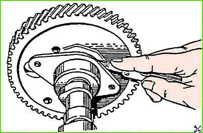
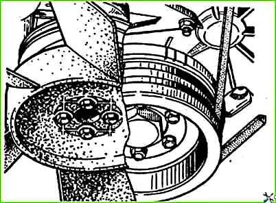
A crankshaft is installed in the block on the outer bearings, to the flange of which the indicator stand is attached.
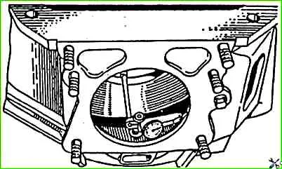
Rotating the crankshaft, check the runout of the hole for the centering collar of the gearbox, as well as the perpendicularity of the rear end of the clutch housing relative to the axis of the crankshaft, as shown in the figure.
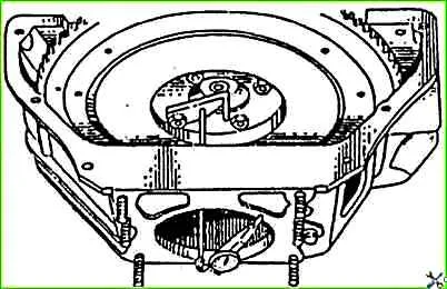
The runout of the crankcase hole and the end should not exceed 0.3 mm, the end - 015 mm.
If the hole runout exceeds the specified value, then loosen the bolts and lightly hit the crankcase flange to ensure its correct installation.
After tightening the bolts, the holes for the dowel pins in the crankcase and block are reamed to repair size.
Blackness in holes is not allowed. After this, pins are pressed into the holes, the diameter of which is 0015-0051 mm larger than the size of the holes.
Runout of the crankcase end is eliminated by scraping.
It should be borne in mind that when checking the above, it is necessary to use an unworn crankshaft and bearings, which must be removed after replacing the crankcase;
- replace defective cylinder liners with new ones as follows:
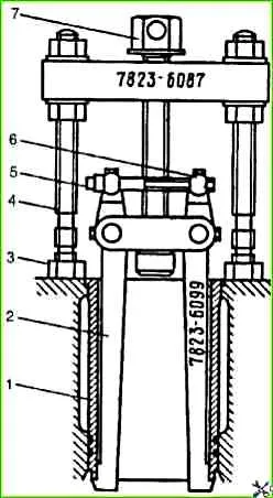
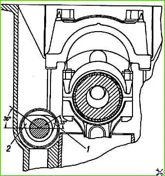
- a) using a combination puller, press out the old sleeve.
Having inserted the puller legs into the engine cylinder, you should rest the pins 4 against the block and move the legs apart with an expansion bolt 5. Then, by rotating the screw 7, press the liner out of the cylinder;
- - b) thoroughly clean the seating surfaces and sealing surfaces on the sleeve and the block from scale and corrosion;
- - c) insert the repaired liner with a soft copper gasket into the cylinder from which it was removed.
The sleeve should enter the cylinder freely, without effort, and protrude above the plane of the block by 002-010 mm.
It is more convenient to first check the amount of recessing of the liner in the cylinder without a gasket. The sinking should be within 020-025 mm;
- - d) secure the sleeve with a holder so that it does not fall out;
- - cut two crankshaft rear seal gaskets from the cord (each 120 mm long), place them in the block and holder;
- - perform subassembly of the crankshaft; to do this, unscrew all plugs of the dirt traps of the connecting rod journals and remove deposits from them.
Rinse and blow out the oil channels and cavities of the dirt traps with compressed air, tighten the plugs to a torque of 38-42 Nm (38-4.2 kgcm);
- check the condition of the working surfaces of the crankshaft.
Nags, burrs and other external defects are not allowed;
- - press ball bearing 80203 AC9 with two protective washers into the rear end of the crankshaft. It is allowed to use a 60203A bearing with one protective washer, and 20 g of Litol-24 lubricant must be placed in the bearing cavity
- - screw the flywheel to the crankshaft. Tighten the nuts to a torque of 76-83 Nm (7.6-8.3 kgcm).
Lock the nuts by bending one of the locking plate's whiskers onto the edge of the nut;
- screw the clutch pressure plate assembly with the casing to the flywheel, having previously centered the driven disk using a mandrel (you can use the input shaft of the gearbox) along the hole in the bearing in the rear end of the crankshaft.
The marks stamped on the pressure plate housing and on the flywheel near one of the holes for the housing mounting bolts must be aligned.
Tighten the bolts to a torque of 20-25 Nm (2.0-2.5 kgcm).
- crankshaft, maho The vic and clutch are balanced as an assembly, and therefore, when replacing one of these parts, dynamic balancing should be performed by drilling out metal from the flywheel.
Balancing of the crankshaft, flywheel and clutch assembly should not begin if the initial imbalance exceeds 200 gsm.
In this case, it is necessary to disassemble the unit and check the balancing of each part separately
- place the rear thrust bearing washer on the first main journal of the crankshaft with an antifriction layer to the crankshaft cheek;
- - compress the crankshaft rear seal packing into the block and holder using a mandrel
- - wipe the main bearing shells and their beds with a clean cloth. Install liners in the bed;
- - lubricate the main bearing shells and the crankshaft journal with clean engine oil and place the crankshaft in the cylinder block;
- - put the main bearing caps on the block studs so that the locking lugs on the upper and lower liners of each cap are on one side, and the numbers stamped on the caps correspond to the bed numbers.
When installing the front main bearing cap, the tail of the rear washer must fit into the groove of the cap.
The end of the front bearing cap must be in the same plane with the end of the cylinder block;
- - put the main bearing caps in place by lightly tapping with a rubber hammer, the caps should fit into the grooves of the cylinder block beds;
- - put washers on the studs, tighten the nuts, apply 2-3 drops (006 g) of Unigerm-9 sealant to the threaded part of the nuts and tighten the nuts evenly.
Final tightening must be done with a torque wrench with a torque of 100-110 Nm (10-11 kg/cm).
If there is no sealant, then the nuts can be locked using the locking plate 24-1005301-01;
- install rubber gaskets into the grooves of the packing holder and coat their side surface protruding from the groove with soapy water.
Place the holder in place and tighten the nuts;
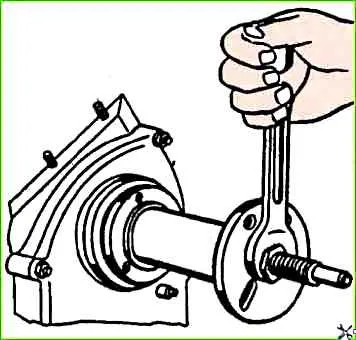
- turn the crankshaft, which should rotate freely with little effort.
You can rotate the crankshaft using the flywheel or using a device consisting of the input shaft of the gearbox with a tetrahedron wrench welded to it or a handle with a square hole.
The device can also be used for centering when installing the clutch driven disc;
- - place the front washer of the thrust bearing with the antifriction layer facing outward so that the pins pressed into the block and cover fit into the grooves of the washer;
- - put on the steel thrust washer of the crankshaft with a chamfer in the inner hole towards the front washer of the thrust bearing;
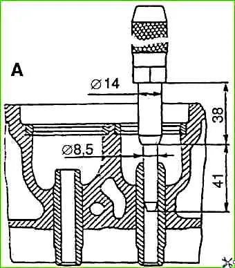
- - press the crankshaft gear all the way and check its axial clearance.
The check is carried out as follows: place a screwdriver (wrench, hammer handle, etc.) between the first crank of the shaft and the front wall of the block and, using it as a lever, press the shaft towards the rear of the engine.
Using a feeler gauge, determine the gap between the end of the rear washer of the thrust bearing and the plane of the shoulder of the first main journal. The gap should be within 0.125-0.325 mm;
- perform subassembly of the connecting rod and piston group
Clean the piston heads and piston ring grooves from carbon deposits.
In case of replacing pistons, liners, piston pins or connecting rods, subassembly of mating pairs should be carried out at a temperature of the parts (20±3)° C.
In bored or new liners, it is necessary to install pistons of the same size groups as the liner. selection from adjacent groups is allowed, and, as when selecting pistons into working liners, selection is made based on the pulling force of a probe tape 0.05 mm thick and 10 mm wide.
The feeler tape is placed in a plane perpendicular to the piston pin axis, along the largest diameter of the piston. The force on the dynamometer connected to the probe tape should be 35-55 N (3.5-5.5 kgf);

- select the piston pin to the connecting rod so that it fits tightly into the connecting rod hole under the force of the thumb, moves freely, without jamming and does not fall out under the influence of its own weight when the axis of the connecting rod hole is located at an angle of 45° (approximately).
The piston pin and connecting rod must be of the same or adjacent size group.
When selecting, the piston pin should be lightly lubricated with engine oil. The size groups of the piston and piston pin must match.
The piston with piston pin, piston rings and connecting rod assembly must be controlled by weight. The difference in weight per engine should not exceed 12 g;
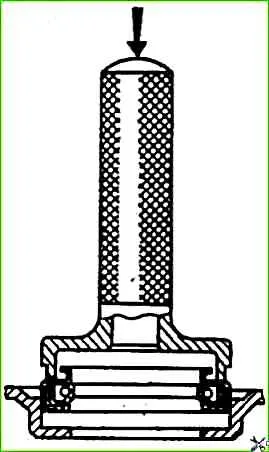
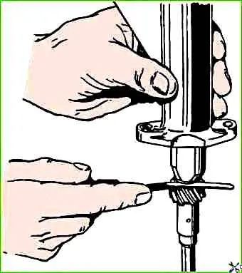
- press the piston pin into the piston and connecting rod using a tool.
Heat the piston to a temperature of 60-88° C, lightly lubricate the piston pin with engine oil.
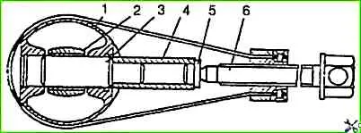
Connect the piston with a guide mandrel 3 to the connecting rod, put the piston pin on the thin end of the mandrel, as shown in, put the bearing 5 on the pin and use screw 6 to push the pin into place.
Pressing a pin into a cold piston can lead to damage to the surface of the holes in the piston bosses, as well as to deformation of the piston itself.
When placing the piston into the cylinder (at the “FRONT” mark on the piston), the hole for lubrication of the cylinder mirror from the lower head of the connecting rod should be facing the direction opposite to the camshaft;
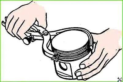
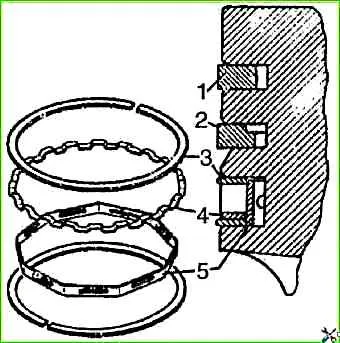
- select piston rings for the cylinder, as shown in the figure.
The gap measured at the joints of the rings should be 03-0.7 mm for compression rings and 0.3-1.0 mm for steel oil scraper ring discs.
In worn cylinders the smallest gap is 0.3 mm;
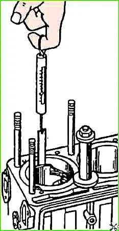
- use a feeler gauge to check the gap between the rings and the wall of the piston groove, as shown in the figure.
Check around the circumference of the piston at several points.
The gap size should be in the range of 0.050-0.870 mm for the upper and lower compression rings, and 0.135-0.335 mm for the assembled oil scraper ring;
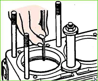
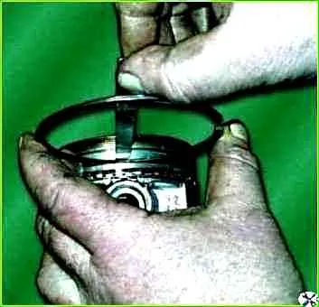
- put safety brass tips on the connecting rod bolts, compress the rings with a crimp or, using a conical ring, insert the piston into the cylinder, as shown in the figure.
Before installing the piston, you should once again make sure that the numbers stamped on the connecting rod and its cover correspond to the serial number of the cylinder, check the correct position of the piston and connecting rod in the cylinder;
- pull the connecting rod by the lower head to the connecting rod journal, remove the brass tips from the bolts, and put on the connecting rod cover.
The connecting rod cap should be installed so that the numbers stamped on the cap and connecting rod face the same direction.
After installing the nuts, apply 2-3 drops (0.06 g) of Unigerm-9 sealant to the threaded part of the nuts and tighten the nuts evenly.
Final tightening of the nuts must be done with a torque wrench to a torque of 68-75 Nm (6.8-7.5 kg/cm).
If used parts are used, it is necessary to remove the remnants of previously applied sealant from the nuts and bolts, degrease them with gasoline and dry them;
- - insert the piston of the fourth cylinder in the same order;
- - turn the crankshaft 180° and insert the pistons of the second and third cylinders;
- - turn the crankshaft several times, which should rotate easily with little effort;
- - subassemble the camshaft in the following order:
- - place the spacer ring and thrust flange on the front end of the camshaft;
- - press on the camshaft gear using the tool and secure it with a bolt and washer. Tightening torque - 55-60 Nm (5.5-6.0 kg/cm);
- - using a feeler gauge inserted between the camshaft thrust flange and the gear hub, set the axial clearance
- - clean the lubrication tube for the timing gears and screw it to the block using a bolt and clamp; camshaft. The gap should be within 0.1-0.2 mm;
- insert the assembled camshaft into the hole of the block, having first lubricated its support journals with engine oil.
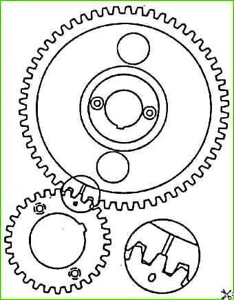
When the gears are engaged, the crankshaft gear tooth with Mark “0” must be against the groove of the camshaft gear teeth.
The lateral clearance in the engagement should be in the range of 0.025-0.1 mm.
If there is a larger or smaller gap, select another pair of gears;
- - through the holes in the camshaft gear, attach the thrust flange to the block with two bolts and spring washers;
- - install the oil deflector on the journal of the front end of the crankshaft with the convex side facing the gear;
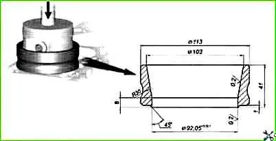
- check the suitability of the cuff pressed into the timing gear cover for further work.
If the cuff has worn working edges or loosely covers the crankshaft pulley hub inserted into the cuff, replace it with a new one.
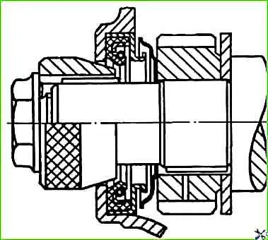
It is recommended to press the cuff into the cover using a mandrel, as shown in the figure.
- place the timing gear cover on the studs of the gasket;
- center the cover along the front end of the crankshaft using a mandrel and tighten all the nuts and bolts securing the cover.
If there is no centering mandrel, the cover can be installed along the crankshaft pulley hub.
The hub must be pressed onto the crankshaft so that its end fits 5 mm into the hole in the cover.
After this, secure the cover with nuts, maintaining the same gap around the circumference between the hub and the cover hole.
The gap should be leveled by lightly hitting the cover with a wooden or rubber hammer. After this, finally secure the cover;
- - remove the centering mandrel and press the pulley hub with the crankshaft damper pulley
- - insert a rubber plug into the keyway and press the key in;
- - screw the pinch bolt into the toe of the crankshaft, after placing a toothed washer on it.
When turning the crankshaft by the coupling bolt, check whether the damper pulley is touching the camshaft cover; - install the oil pump assembly with the oil receiver;
- - install the oil pump drive and ignition distributor sensor in the following order:
- turning the crankshaft, align the third mark on the damper disk with the indicator rib on the camshaft cover.
The camshaft cams actuating the valves of the first cylinder must be directed with their apexes in the direction opposite to the pushers (towards the oil sump) and located symmetrically
- - check the axial clearance between the drive housing and the gear using a feeler gauge
- - put a gasket on the drive mounting studs; The gap should be within 0.15-0.40 mm;
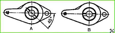
- turn the drive shaft to the position shown in “A” and place the drive in the block socket.
When inserting the drive into the socket, it is necessary to slightly turn the oil pump shaft so that the end of the drive shaft enters the hole in the pump shaft.
The drive should be inserted without significant effort.
In a correctly installed drive, the slot in the shaft bushing should be parallel to the axis of the motor and offset from the motor, as shown in "B";
- secure the drive;
- - check for clearance in the camshaft and drive gears;
- - lubricate the joints of the lower flange of the cylinder block with the timing gear cover and the packing holder with glue-sealant “Elastosil 1Z7-8Z” or UN-25 paste;
- - install the oil pan gasket on the lower flange of the cylinder block;
- - install the oil sump on the studs and secure it with nuts and washers, tightening the nuts evenly;
- - install and bolt the lower part of the clutch housing;
- - clean the combustion chambers and cylinder head channels from soot and deposits, wipe and blow with compressed air;
- - lap the valves using a lapping paste made up of one part M-20 micropowder and two parts I-20A oil.
Before starting grinding, you should check for warping of the valve plate and burnout of the valve and seat.
If these defects are present, it is impossible to restore the tightness of the valve by grinding alone and the seat must first be ground and the damaged valve replaced with a new one.
If the gap between the valve and the bushing exceeds 0.25 mm, then the tightness cannot be restored either. In this case, the valve and bushing should be replaced with new ones.
Valves (for spare parts) are produced in a standard size, and guide bushings are produced with an internal diameter reduced by 0.38 mm (for reaming them to the final size after pressing into the cylinder head).
The worn guide bushing is pressed out using a mandrel.
Valve seats are removed by milling with a carbide countersink.
Repair seats have an outer diameter 0.25 mm larger than standard ones, so the seat sockets are bored to the following dimensions: for the intake valve seat - 49.25+0.025 mm, for the exhaust valve - 42.25+0.025 mm.
Before assembly, the guide bushing seats must be cooled in carbon dioxide (dry ice), and the cylinder head must be heated to a temperature of 160-175° C.
During assembly, seats and bushings should be inserted into the head sockets freely or with light force.
Pressing in new bushings for the intake and exhaust valves is carried out until they protrude 20 mm above the head. After pressing, expand the holes of the bushings to a diameter of 9+0.022 mm, and grind the seat chamfers, centering them along the hole in the bushing.
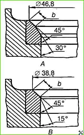
When grinding, ensure that the chamfer on the valve seat is concentric with the hole in the bushing within 0.05 mm. The chamfers are ground at an angle of 45°.
Chamfer outer diameter The seat for the intake valve should be 46.8 mm, and for the exhaust valve - 38.8 mm.
The width of the chamfer should be 1.8 - 2.3 mm at the intake valve seat, 2.3-2.5 mm at the exhaust valve.
The width of the chamfer is achieved by grinding the intake valve seat bore at an angle of 30°, as shown in "A", and the exhaust valve - at an angle of 15°, as shown in "B". The chamfer should be the same around the entire perimeter.
After grinding the seats and grinding the valves, thoroughly clean all gas channels and blow them with compressed air so that no abrasive dust remains;
- - coat the valve stems with a thin layer of colloidal graphite diluted in engine oil, or lubricate with oil
- - press oil seals onto the valve guide bushings, insert the valves into the bushings according to the marks made and assemble them with the springs. Make sure that the crackers fit into the annular groove of the valves;
- rub graphite powder on both sides of the cylinder head gasket and put it on the studs.
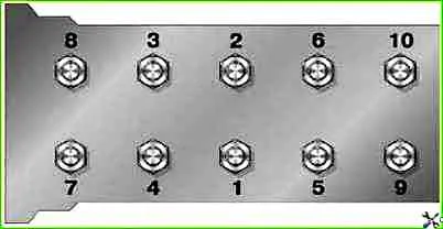
Install the head and secure it with nuts and washers. Tighten the nuts with a torque wrench to a torque of 83-90 Nm (8.3-9.0 kg/cm), maintaining order
- clean with wire and blow out with compressed air the holes in the rocker arms, in the rocker axis and adjusting screws, in the fourth main post of the rocker axis and the oil channels in the cylinder head.
Check that the rocker arm bushings are securely seated.
If the fit is loose during operation, the bushing may move and block the lubrication hole of the valve lifter rod. Such bushings must be replaced;
- subassemble the rocker arm axis.
Before installing each rocker arm, lubricate its bushing with engine oil;
- - insert the pushers into the sockets according to the marks on them. Pre-lubricate the pushers and holes in the block with engine oil;
- - insert the rod assembly with tips into the holes in the cylinder head;
- - install the assembled rocker arm axle on the studs and secure with nuts and washers. The adjusting bolts with their spherical part should rest on the sphere of the upper tip of the rod;
- - set the gaps between the ends of the valve stems and the tips of the rocker arms. The gap between the rocker arms and the first and eighth valves is 0.35-0.40 mm, the gap between the remaining rocker arms and valves is 0.40-0.45 mm.
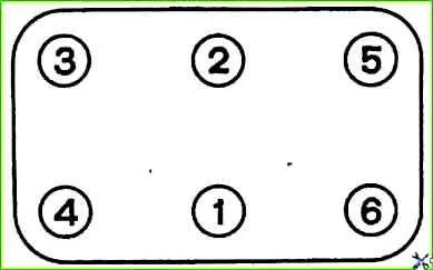
- - install the gasket and rocker cover and secure them with bolts and washers, ensuring correct tightening, according to the figure.
- - lubricate and place the clutch release clutch on the front cover of the gearbox.
- - install and secure the gearbox;
- - install the clutch release fork;
- - install engine parts and assemblies
")

")
")
")
")
")
")
")