Install the secondary shaft in a vertical position
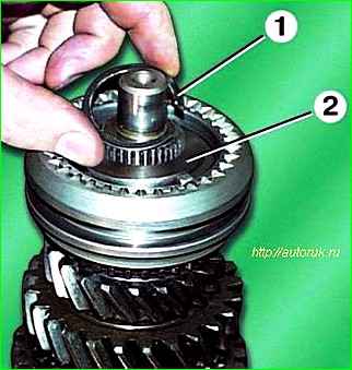
Remove retaining ring 1 and spring ring 2 of the 3rd and 4th gear synchronizer
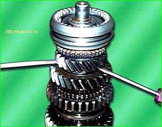
Pry up the 3rd gear gear with two screwdrivers and move it up together with the synchronizer.
Remove the 3rd and 4th gear synchronizer.
Then remove the 3rd gear with the locking ring.
Mark the locking ring relative to the coupling.
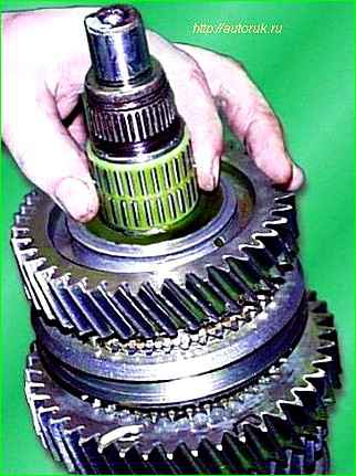
Remove the 3rd gear needle bearing and mark it.
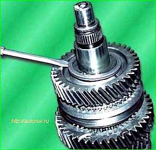
Remove the retaining ring of the secondary shaft thrust half-rings.
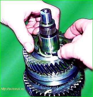
Remove the two thrust half-rings.
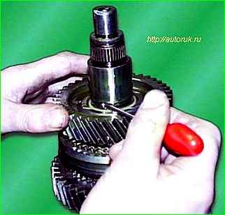
Remove the locking ball.
Remove the 2nd gear with the locking ring.
Mark the locking ring relative to the coupling
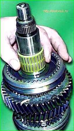
Remove the 2nd gear needle bearing and mark it
Remove the 1st and 2nd gear synchronizer and the 1st gear.
The operation is similar to removing the 3rd and 4th gear synchronizer and 3rd gear gear
Turn over the shaft.
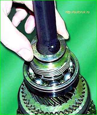
Remove the circlip and spring ring of the speedometer drive gear.
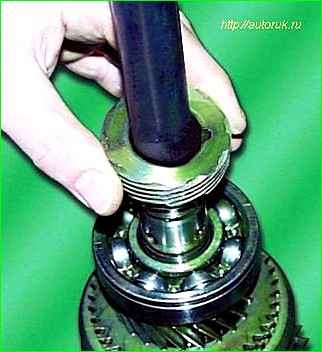
Remove the speedometer drive gear by first removing the locking ball
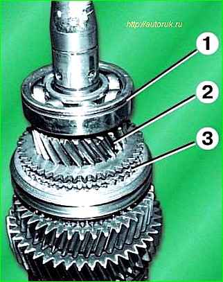
Compress ball bearing 1 and remove the thrust washer. Remove gear 2 of the 5th gear with blocking ring 3.
Mark the locking ring in relation to the coupling.
Remove the needle bearing and spacer. Mark the needle bearing.
Remove the retaining ring.
Remove the 5th gear and reverse synchronizer and the reverse gear.
The operation is similar to removing the 3rd and 4th gear synchronizer and 3rd gear gear
Assembling the secondary shaft
The secondary shaft is assembled in the reverse order of disassembly.
Before assembly, lubricate the secondary shaft parts with a thin layer of transmission oil.
Make sure that when assembling the synchronizer blocks fit into the grooves of the blocking rings.
The ball bearing must be pressed onto the shaft, applying force only to the inner ring of the bearing.


