Checking and adjusting the valve clearance must be done on a cold engine (coolant temperature 20˚С ± 5°С), with the cylinder head installed on the block
Remove the engine cover.
Remove the air filter
Remove the resonator.
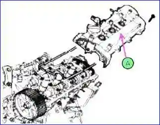
Remove the cylinder head cover.
- - Disconnect the ignition coil connector and remove the ignition coil.
- - Remove the cylinder head cover.

Set the piston of the first cylinder to the top dead center position during the compression stroke, to do this:
- - Rotate the crankshaft pulley and align the notch on the pulley with the mark on the plate, as shown in the figure.
- - Check and make sure that the mark on the camshaft sprocket (A) is in a straight line with the surface of the cylinder head. If the hole does not coincide with the mark, you need to rotate the crankshaft 360˚.
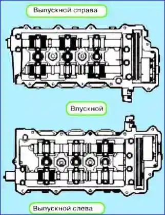
Measure the valve clearance, to do this:
Check the valves marked in the figure (cylinder No. 1, TDC/compression), measure the valve clearance.
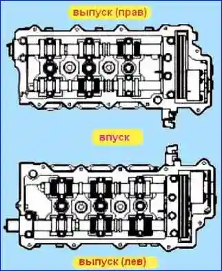
- Use a set of feeler gauges to measure the clearance between the cam and the camshaft base circle. Record the measurements.
They will be needed to determine the required position of the replaced cam.
Engine coolant temperature 20˚C. Maximum permissible clearance:
0.10 - 0.30 mm (inlet), 0.20 - 0.40 mm (exhaust).
- - Rotate the crankshaft pulley 360˚ and align the groove with the “T” mark on the lower timing chain cover
- - Check the valves marked in the figure (cylinder no. 4, TDC/compression). Measure the valve clearance.
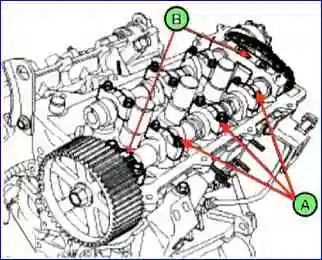
Adjust the clearance in the exhaust and intake valves, to do this:
Install the piston of cylinder No. 1 to TDC, compression.
- - Place a mark on the timing belt and camshaft sprockets.
- - Remove the camshaft bearing caps (A, B).
- - Remove the camshaft assembly.
- - Remove the hydraulic compensator.
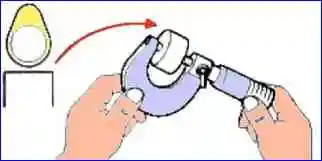
- - Measure the thickness of the cam with a micrometer
Calculate the thickness of the new cam, the value should not exceed the standard one.
Valve clearance (at engine coolant temperature: 20˚C). T - Thickness of the removed cam, A - measured valve clearance, M - thickness of the new cam.
Inlet: M = T + (A – 0.20 mm).
Issue: M = T + (A - 0.25 mm).
• Select the thickness of the new cam as close as possible to the standard value.
The size of the gasket should be from 3 to 3.6 ± 0.015 mm, size No. - 41.
Apply engine oil to the edges of the cam.
- Install the intake and exhaust camshafts
- Install the bearing cap
- Install the timing belt.
- Rotate the crankshaft 2 turns clockwise and move the marks (A) of the crankshaft sprocket and camshaft (A).
- Check the valve clearance again.
Valve clearance (at engine coolant temperature 20˚C).
- Intake: 0.17 - 0.23 mm.
- Output: 0.27 - 0.33 mm.


