Defection and repair of the ZMZ-406 cylinder block
To determine the technical condition and repair of the cylinder block, remove the engine from the car and disassemble it
Remove the cylinder head, crankshaft, connecting rod and piston group, oil sump and oil pump, as well as all attachments
Inspect the cylinder block. If cracks are found, replace it.
Check the tightness of the cooling jacket of the block using the pressure test method: plug all holes in the block with wooden plugs, except one, to which connect the compressed air supply hose (You can also use rubber and plastic plugs of a suitable size).
Dip the block into a bath of water and apply compressed air at a pressure of 1.5 atm.
In places where the seal is broken, air bubbles will escape. If a leak is detected, replace the unit.
In the same way, check the tightness of the oil passages of the block.
Inspect the cylinders.
If there are scuffs and other defects on the cylinder bore, bore the cylinders to the repair size and hone them.
There are two repair sizes of cylinders indicated in the table.
Spare parts include pistons and piston rings of appropriate repair sizes.
Note:
All cylinders must be bored to the repair size, even if defects are found in only one.
Check the clearances between the cylinders and pistons.
The nominal gap is 0.024-0.048 mm, the maximum permissible is 0.25 mm.
Cylinders and pistons are divided by diameter into five size groups: A, Б, В, G, D.
The letter designating the cylinder group is painted on the left outer side of the block opposite each cylinder.
The clearance can be determined by measuring the diameters of the piston and cylinder.
The piston diameter is measured in a plane perpendicular to the piston pin axis, at a distance of 8.0 mm below the piston pin axis.
The diameter of the cylinder is measured in at least three zones within 15-100 mm from the top surface of the block (in two mutually perpendicular directions).
Size groups of cylinders and pistons
Group "A", cylinder diameter, mm:
- - nominal size 92.036 – 92.024;
- - 1st repair size * 92.536 – 92.524;
- - 2nd repair size ** 93.036 – 93.024
Group “A”, piston diameter, mm:
- - nominal size 92,000 – 91,988;
- - 1st repair size 92.500 – 92.488;
- - 2nd repair size 93,000 – 92,988
Group "Б", cylinder diameter, mm:
- - nominal size 92.048 – 92.036;
- - 1st repair size 92.548 – 92.536;
- - 2nd repair size 93.048 – 93.036
Group “Б”, piston diameter, mm:
- - nominal size 92.012 – 92.000;
- - 1st repair size 92.512 – 92.500;
- - 2nd repair size 93,012 – 92,000
Group “B”, cylinder diameter, mm:
- - nominal size 92.060 – 92.048;
- - 1st repair size 92.560 – 92.548;
- - 2nd repair size 93.060 – 93.048;
Group “B” piston diameter, mm:
- - nominal size 92.024 – 92.012;
- - 1st repair size 92.524 – 92.512;
- - 2nd repair size 93.024 – 92.012
Group "G", cylinder diameter, mm:
- - nominal size 92.072 – 92.060;
- - 1st repair size 92.572 – 92.560;
- - 2nd repair size 93.072 – 93.060
Group "G", piston diameter, mm:
- - nominal size 92.036 – 92.024;
- - 1st repair size 92.536 – 92.524;
- - 2nd repair size 93.036 – 92.024
Group "D", cylinder diameter, mm:
- - nominal size 92.084 – 92.072;
- - 1st repair size 92.584 – 92.572;
- - 2nd repair size 93.084 – 93.072
Group "D", piston diameter, mm:
- - nominal size 92.048 – 92.036;
- - 1st repair size 92.548 – 92.536;
- - 2nd repair size 93.048 – 92.036
* 1st repair size increased by 0.5 mm
** 2nd repair size increased by 1.0 mm
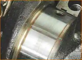
Check the clearances between the main bearing shells and the crankshaft journals. The gap should be in the range of 0.019–0.073 mm.
The clearances can be calculated by measuring the diameters of the crankshaft journals and journal holes with the main bearing shells and caps installed, or by measuring them using a calibrated plastic wire.
Measure the gaps in the following order:
Clean the crankshaft journals and bearing shells.
Place the crankshaft on the bed of the main bearings with the shells installed.

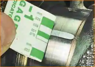
Place pieces of calibrated plastic wire on the crankshaft journals.

Install the main bearing caps with the liners installed in them, tighten the bolts securing the caps and tighten to a torque of 100 Nm (10 kgf m). In this case, it is forbidden to turn the crankshaft.
Remove the main bearing caps and, by flattening the wire, determine the gap using the scale marked on the wire package.


