The compressor is designed to compress air and then pump it into the pneumatic system.
The compressor is installed on the left side of the engine timing gear cover.
The compressor receives drive through an intermediate movable gear, as well as through a gear that is made integral with the compressor crankshaft.
The figure shows the installation locations of the parts and their designations according to the spare parts catalog.
We look at the figure and the table shows the decoding of the part.
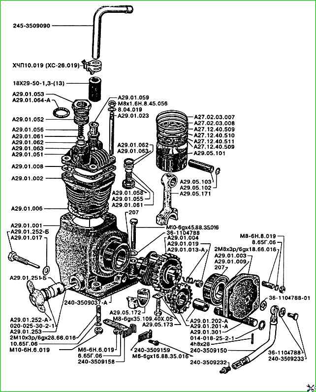
ZIL-5301 compressor parts according to the catalog
Part No. Part name
- 014-018-25-2-1 Ring
- 020-025-30-2-1 Ring
- 10.65G.06 Washer
- 18x29-50-1.3-(13) Sleeve part
- 207 Bearing
- 240-3509037-A Gasket
- 240-3509150 Oil line
- 240-3509158 Clamp
- 240-3509159 Clamp
- 240-3509232 Fitting
- 240-3509233 Fitting bolt
- 245-3509090 Pipe
- 2M10x3p/6gx28.66.016 Stud
- 2M8x3p/6gx18.66.016 Stud
- 36-1104788 Gasket
- 36-1104788-01 Gasket
- 4h8x28 Pin
- 6.65G.06 Washer
- 8.04.019 Washer
- 8.65G.06 Washer
- A27.02.03.007 Compression ring
- A27.02.03.008 Compression ring
- A27.12.40.509 Segment
- A27.12.40.510 Expander
- A27.12.40.511 Expander
- A29.01.000 Compressor
- A29.01.001 Crankcase
- A29.01.002 Cylinder
- A29.01.003 Cover
- A29.01.004 Shaft crankshaft
- A29.01.006 Cylinder gasket
- A29.01.008 Gasket
- A29.01.009 Gasket
- A29.01.013-A Spring
- A29.01.017 Gasket
- A29.01.019 Cover seal
- A29.01.023 Stud
- A29.01.050 Cylinder head
- A29.01.051 Cylinder head
- A29.01.052 Valve body
- A29.01.053 Plug
- A29.01.055 Spring valve
- A29.01.056 Valve spring
- A29.01.058 Valve body
- A29.01.059 Fitting
- A29.01.061 Valve
- A29.01.062 Valve seat
- A29.01.063 Gasket
- A29.01.064-A Gasket
- A29.01.180 Piston ring set
- A29.01.200-A Gear
- A29.01.201-A Gear
- A29.01.202-A Bushing
- A29.01.250-A Control shaft
- A29.01.251-B Shaft
- A29.01.252-A Lever
- A29.01.252-B Bolt
- A29.01.253 Pin
- A29.01.301 Pinion axle
- A29.05.100 Piston and connecting rod
- A29.05.101 Piston
- A29.05.102 Retaining ring
- A29.05.103 Piston pin
- A29.05.170 Connecting rod
- A29.05.171 Connecting rod
- A29.05.172 Connecting rod cap
- A29.05.173 Lock washer
- M10-6gx45.88.35.016 Bolt
- M10-6N.6.019 Nut
- M6-6gx16.88.35.016 Bolt
- M6-6N.6.019 Nut
- M8-6gx35.109.40X.05 Bolt
- M8-6N.8.019 Nut
- M8x1.6N.8.45.056 Nut
- ХЧП10.019(ХС-26.019) Clamp
The friction surfaces of the compressor are lubricated by splashing oil, which comes from the diesel distribution gears.
When the air pressure in the receiver reaches 0.73 - 0.74 MPa, the pressure regulator is triggered, and the compressor is switched off.
Air from the compressor through the regulator comes out into the atmosphere without back pressure, due to which the compressor is unloaded.
When the pressure in the receiver drops to 0.64 - 0.67 MPa, the regulator turns on the compressor, and compressed air enters the system again.
")

")
")
")
")
")
")
")