Disassembling the gearbox input shaft
The dismantling of shafts is discussed in the article - “Repair of the gearbox of a Lada Kalina”
Clamp the input shaft in a vice with soft metal jaw linings.

Pry up the rear ball bearing with two mounting blades and press it together.

Through the bit we strike the end of the inner ring of the front roller bearing

And press the ring
Disassembling the secondary shaft
Clamp the secondary shaft in a vice with soft metal jaw linings.

Insert two mounting blades into the gap between the ends of the inner ring of the front shaft bearing and the main gear drive gear (to avoid damaging the gear teeth, you can place soft metal spacers under the mounting blades).

Resting the mounting blades on the gear.
Press the inner ring of the front bearing.

Use snap ring pliers to open the lock ring

And remove the retaining ring from the front end of the shaft

Hooking the first gear driven gear with a three-jaw puller

Compress the drive gear of the main gear.
If there is no puller, place stops under the driven gear of the first gear and compress the drive gear of the main gear, striking the end of the shaft with a hammer with a soft metal tip.

Use snap ring pliers to open the lock ring

And remove the retaining ring of the first and second gear synchronizer clutch hub.

Prying the driven gear of the second gear with two mounting blades, we press the hub of the synchronizer clutch of the first and second gears from the shaft.

Remove the first and second gear synchronizer assembly with the second gear driven gear.
Disconnect the driven gear of the first gear and the synchronizer of the first and second gears.
Turn over the shaft in a vice

Having placed a stop under the screw of a two-jaw puller on the end of the shaft, we press the rear shaft bearing with the puller

Remove the bearing

Remove the thrust washer

Remove the fourth gear driven gear

Using pliers, open the retaining ring of the third and fourth gear synchronizer clutch hub

Remove the ring

Having rested the third gear gear on the jaws of a vice (with pads made of soft metal), we apply hammer blows through a wooden block to the end of the shaft, pressing the synchronizer clutch hub of the third and fourth gears from the shaft.

Remove the third and fourth gear synchronizer assembly with the third gear driven gear.
Disconnect the third gear driven gear and the third and fourth gear synchronizer.
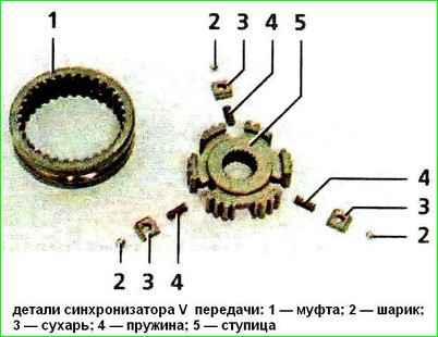
Disassembling and assembling the synchronizer
Synchronizers - second, third, fourth and fifth gears are disassembled and assembled in the same way.
We show disassembly and assembly of a synchronizer using the example of a fifth gear synchronizer.
Before disassembling, we mark the blocking rings and their position relative to the synchronizer clutch.
Remove the blocking rings.
We mark the position of the hub relative to the coupling and the position of the crackers relative to the grooves of the hub, so that during subsequent assembly they will be installed in their original places.

To disassemble the synchronizer, carefully slide the coupling along the hub, holding the balls with your hand to prevent them from “shooting out.”
Before assembly, we inspect the synchronizer parts.
Kinks and chips on the splines of the hub and coupling, the gear rims of the locking rings and the coupling are unacceptable.
We replace defective parts with new ones. If there is significant wear on the working conical surface of the blocking ring (the minimum permissible axial clearance between the ends of the gear rims and the blocking ring is 0.6 mm), it must be replaced.
For ease of assembly of the synchronizer, generously lubricate the springs, crackers and balls with grease.
Putting the hub on the workbench, insert springs into the hub sockets and crackers into the grooves in accordance with the previously applied marks.

We insert the assembled hub into the coupling, orienting it so that when the ball is subsequently installed, it would be located exactly in the middle part of the coupling groove - in its deepest place.

Insert balls into the holes of the crackers.

Pressing each ball in turn with a screwdriver, we slide the hub along the coupling splines.
When installing the synchronizer shaft, the grooves on the coupling and hub must face:
- - for the first and second gear synchronizer - to the first gear gear;
- - for the third and fourth gear synchronizer to the third gear;
- - for the fifth gear synchronizer - to the thrust plate of the shaft bearings.

Grooves on the coupling and synchronizer hub
Disassembling the differential
Clamp the driven gear of the main gear in a vice with soft metal jaw linings.

Using a 17mm socket, unscrew the eight bolts securing the gear to the differential box.
Resting the driven gear of the main drive on the jaws of a vice (with soft metal linings).
Use a hammer with a plastic tip (or a soft metal tip) to knock the differential box out of the driven gear.

Inserting a blunt chisel into the gap between the end of the inner bearing ring and the differential box, we strike the chisel, increasing the gap.

Then, installing two mounting blades into the resulting gap.

We press the bearing with them.

Remove the speed sensor master ring.
Attention! During subsequent assembly, the tabs of the drive ring must be installed in deeper grooves at the end of the differential box.

Rotate and remove the wheel drive gears from the differential box

Using lock ring pliers, remove the lock ring from the satellite axis

Remove the pinion axle and pinion gears from the differential box
Clamp the main drive driven gear in a vice with soft metal jaw linings.
")

")
")
")
")
")
")
")