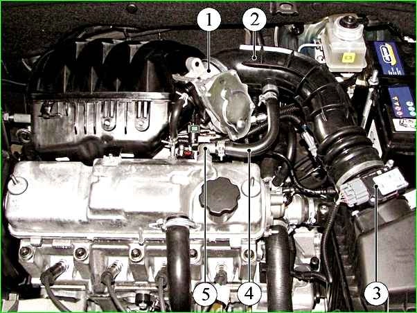
Removing the throttle assembly and removing the Lada Granta receiver
We remove the throttle assembly for cleaning and also when removing the receiver and replacing sealing gaskets
Remove the air supply hose to the throttle body

Use a Phillips screwdriver to loosen the clamp securing the air supply hose to the throttle body

Remove the hose from the throttle body pipe and move it to the side

Press the lock of the SUD wire block and disconnect the block from the connector of the control unit
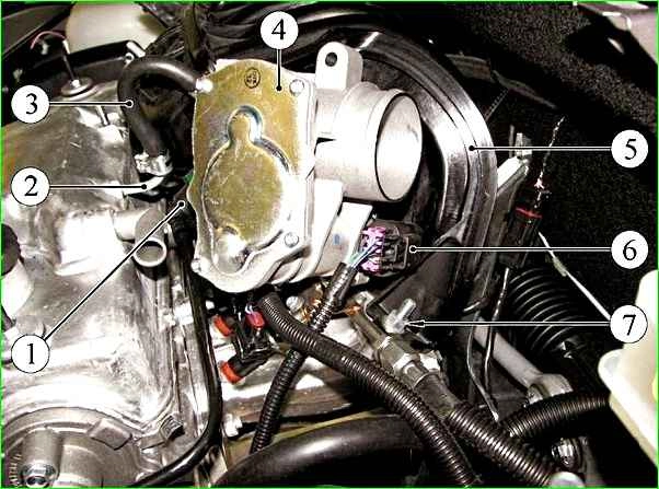
Disconnecting the harness block

Using a 5mm hex wrench, unscrew the four screws securing the throttle assembly to the receiver flange
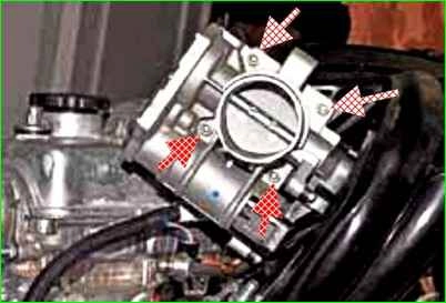
Remove the throttle assembly


The connection of the assembly is sealed with a rubber gasket installed in the groove of the receiver flange

The throttle assembly control unit body bears its mark.
If necessary, rinse with gasoline and clean the throttle valve from dirt.
Installing the throttle assembly in reverse order
Removing the receiver
Usually the receiver is removed to replace its seals when removing the inlet pipe.

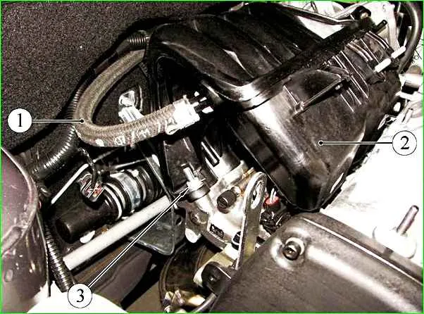
Remove the hose of the main circuit of the crankcase ventilation system from the pipe of the cylinder head cover

Removing the receiver bracket
Remove the air supply hose to the throttle assembly and remove the throttle assembly as described above

On the left side of the receiver, squeeze the clamps of the tip of the canister purge valve tube and disconnect the tip from the receiver fitting

Using a Phillips screwdriver, loosen the clamp securing the idle circuit hose of the crankcase ventilation system

Remove the hose from the receiver fitting

On the right side of the receiver, using pliers, loosen the tightening of the tape clamp securing the vacuum brake booster hose

Remove the hose from the receiver fitting

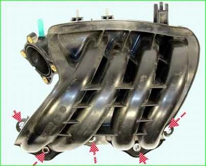
Using a 13mm high socket, unscrew the five nuts securing the receiver to the intake pipe, one of them is the upper right mounting nut

One nut of the upper left fastening
Two nuts for the lower side fastenings and one nut for the central fastening

Slide the receiver off the intake pipe studs and remove it from the engine compartment
We replace the receiver gaskets if they have lost elasticity or are deformed.

Install the receiver in reverse order.
Tighten the receiver nuts evenly to a torque of 20-24 Nm
")

")
")
")
")
")
")
")