Remove the gearbox (see “Removing and installing the Lada Granta gearbox”)
We clean the outside of it from dirt (do not allow dirt to get inside the box)
Removing the speed sensor

For the convenience of further disassembling the gearbox, screw two nuts onto the clutch housing mounting pin and unscrew the pin from the clutch housing.
Install the gearbox on the workbench with the clutch housing facing down.

Using a 13mm spanner, unscrew the reverse gear fork lock plug.

Remove the retaining spring from the hole in the crankcase.

Using a magnet, remove the locking ball.
We unscrew the reverse gear lock solenoid and the reverse light switch from the holes in the gearbox housing.

Using a 13 mm spanner, unscrew the nut securing the rear cover of the gearbox housing, which simultaneously secures the clutch release cable bracket.

Using a 17 mm spanner, unscrew the bolt securing the clutch release cable bracket.

Remove the bracket.

Using a 13mm spanner, unscrew five more nuts securing the rear crankcase cover

Tapping with a plastic-tipped hammer or regular hammer through a soft metal mandrel on the lid lugs

Remove the cover from the studs.
To loosen the shaft nuts, it is necessary to stop the shafts from turning by engaging two gears at once.
To do this, press the gear selector rod all the way and engage third gear.

Using a 10mm spanner, unscrew the bolt securing the “V” gear fork.

Using a soft metal drift, we strike the fork, including “V” gear.

Use a beard to straighten the places where the flanges of the primary and secondary shaft nuts are cored.

Use a 32mm socket with a powerful wrench to unscrew the shaft nuts

Use a screwdriver to pry off the driven gear “V” of the transmission and remove the “V” transmission assembly

Remove the "V" gear shift fork.

Having marked the position of the synchronizer blocking ring relative to the clutch, remove the gear "V" transmission with the synchronizer blocking ring.

Remove the synchronizer blocking ring.

Remove the synchronizer thrust plate.

Use a screwdriver to pry off the bushing of the driven gear “V” of the transmission.

Remove the gear from the secondary shaft.

Insert one or two screwdrivers into the gap between the thrust plate and the drive gear “V” of the transmission.

Using a screwdriver to pry up the gear, press it off the input shaft.

Remove the thrust ring from the secondary shaft.

Use an impact screwdriver with a Phillips head RNZ to unscrew the four screws securing the thrust plate of the bearings.

Special lock washers are installed under the screw heads.
Remove the plate

Using a 13 mm spanner, unscrew the three plugs of the gear shift fork rod clamps.

Use a magnetic screwdriver to remove the retaining balls.

Use two screwdrivers to open the ends of the retaining ring of the rear bearing of the input shaft and remove the ring from the groove in the crankcase.

In the same way, remove the retaining ring of the rear bearing on the secondary shaft.

Using a 13mm spanner, unscrew one bolt and thirteen nuts securing the gearbox housing to the clutch housing.
Insert a screwdriver into the groove at the junction of the mating planes of the crankcases.

Carefully lift the gearbox housing and remove it


Remove the magnet from the crankcase recess.

Using a 10mm spanner, unscrew the bolt securing the 1st-2nd gear shift fork to the rod

Lift the rod up and remove the fork from the groove of the synchronizer sliding clutch

Using a 10mm spanner, unscrew the bolt securing the 3rd-4th gear shift fork to the rod

Use a screwdriver to remove the rod lever from engagement in the gear shift mechanism.

Lift the rod up and remove the fork from the groove of the synchronizer sliding clutch.

By turning the rod of the 1st gear shift fork, we remove the rod lever from engagement in the gear shift mechanism.

Remove the axis of the reverse gear intermediate gear.

Remove the intermediate gear of the rear transmission xode.

Using a 10mm socket, unscrew the three bolts securing the gear shift mechanism.

Removing the gear shift mechanism

We simultaneously remove the primary and secondary shafts from the roller bearings of the clutch housing.

Take out the differential assembly.
The cardan joint of the gear shift rod can be replaced without removing the gearbox on the car by disconnecting the gearbox control rod from the joint shank.
For clarity, we show the removal of the hinge on the removed gearbox.

Move the protective cover from the rod hinge and unscrew the conical hinge screw with a 10mm head.

Remove the hinge and the protective cover of the hinge from the rod.

If you need to remove the gear switch or its rod, use a 10 mm socket to unscrew the conical screw securing the gear switch.

Pull the rod out of the crankcase hole and remove the gear switch from the rod.

Use a screwdriver to remove the rollers of the front bearing of the secondary shaft from the separator.

Remove the bearing cage.

Use the hook of the impact puller to hook the shoulder of the outer ring of the bearing

And press out the outer ring of the bearing.
Remove the oil pan.
In the same way we press out the outer ring of the input shaft bearing.

Use a suitable piece of pipe to knock out the wheel drive oil seal from the clutch housing

Through the beard, nanosim blows to the end of the outer ring of the differential bearing.

And press out the ring
In the same way, we knock out the oil seal and the outer ring of the differential bearing from the gearbox housing. We take out the adjusting ring
Disassembly and assembly of the input shaft, secondary shaft, differential and synchronizer will be discussed in the article - “Disassembly and assembly of shafts, differential and synchronizer of the Lada Granta gearbox.”
Assembling the gearbox
To check the technical condition of the gearbox parts, we thoroughly clean and rinse them. The surfaces of the housings for bearings and rods must not be damaged.
Damage is not allowed on the threaded part of the shafts, on the splines and surfaces of the shafts for gears and bearings.
The seating surfaces of the gears should be free of burrs and signs of wear. No chipping or excessive wear of gear teeth is allowed.
Ball and roller bearings must not have damage to the raceways, cages, balls and rollers, as well as cracks and chips on the rings.
The rotation of the bearing rings must be smooth, without jamming. We replace damaged bearings with new ones. Deformation of the rods and gear forks is not allowed.
The working surfaces of the forks in contact with the grooves of the sliding clutches of the synchronizers should not have excessive wear.
The rods in the crankcase holes must move freely, without jamming.
Assemble the gearbox in reverse order.
When assembling the differential, lubricate the satellites and drive gears with transmission oil.
We mount the differential bearings with preload.
The tension is ensured by selecting the thickness of the adjusting ring installed in the gearbox housing housing under the outer ring of the differential bearing.
Selection of the thickness of the adjusting ring is necessary if replacing one of the following parts: differential box, differential bearing, clutch housings and gearbox.
The differential bearing preload should be 0.25 mm.
To ensure this tension, it is necessary to select the correct thickness of the adjusting ring.
When selecting an adjusting ring, you will need: an adjusting ring 1.25 mm thick, a stand with a dial indicator, a mandrel.
Insert the installation ring into the socket of the gearbox housing and press in the outer ring of the differential bearing using a mandrel of a suitable diameter.
In the same way, press the outer ring of the differential bearing into the clutch housing.
We install the differential into the gearbox housing, after which we install the clutch housing and tighten the housings with nuts (at least three equally spaced).
Rotate the differential several turns to self-install the bearings.
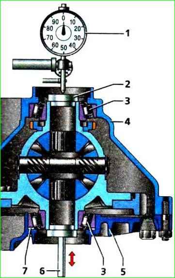
We install a mandrel (in the form of a plug) on the end of the differential, and a stand with an indicator on the clutch housing, so that the leg rests against the mandrel, and create a tension on the indicator of 1 mm.
Move the differential up and take indicator readings.
The thickness of the adjusting ring is calculated using the formula:
S=A+B+C
- where S is the thickness of the adjusting ring, A is the amount of axial movement of the differential, B is the amount of preload of the differential bearings, C is the thickness of the adjusting ring (1.25 mm).
After determining the thickness of the adjusting ring, disconnect the gearbox and clutch housings, remove the differential, press out the outer bearing ring from the gearbox housing and replace the adjusting ring with the selected adjusting ring.
Spare parts include adjusting rings with a thickness from 1.65 mm to 2.65 mm, in increments of 0.05 mm.
After installing the differential in the clutch housing, it is necessary to secure one of the wheel drive gears with a mandrel (plug) so that they do not move from their seats during further assembly.
When assembling the gear switch and the hinge of the switch rod with the rod, first degrease the threaded holes in the hinge body and switch, as well as the conical screws securing them.
Before screwing, apply thread sealant to the threads of the screws.
Outer rings of roller bearings of shafts, oil seals of primary We press the shaft, drives and gear selector rod with mandrels or suitable pipe sections. Apply a thin layer of transmission oil to the working edges of the oil seals.
If the wheel drive oil seals have oil drainage notches, then install an oil seal with a right notch in the clutch housing (for right-hand drive), and an oil seal with a left notch in the gearbox housing (for left-hand drive).
The arrows on the oil seal housings must coincide with the direction of rotation of the drives when the vehicle moves forward.
When assembling the secondary shaft, lubricate the parts with transmission oil. We replace the locking rings of the synchronizer hubs with new ones.
We press the synchronizer hubs, the inner ring of the roller bearing, the ball bearing and the drive gear of the main gear onto the shaft using mandrels or suitable pipe sections.
After assembling the secondary shaft, we check the operation of the synchronizers, for which we manually move the synchronizer clutches to the position of engaging the corresponding gears.
Press the inner ring of the roller bearing and the ball bearing onto the input shaft.
Before installing the shafts, we engage the gear teeth of both shafts and in this position install the shafts into the clutch housing.
Before assembling the gearbox housing with the clutch housing and the rear cover, apply a thin layer of sealant around the perimeter of the mating surfaces.