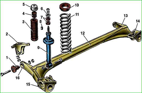
The rear suspension of the car is semi-independent, made on an elastic beam with trailing arms, coil springs and double-acting telescopic shock absorbers
The rear suspension beam consists of two trailing arms connected by a U-shaped cross member. This cross-section provides the connector (cross member) with greater bending rigidity and less torsional rigidity.
The connector allows the levers to move relative to each other within small limits.
The levers are made of pipes of variable cross-section, this gives them the necessary rigidity
Brackets for attaching the shock absorber, rear brake shield and wheel hub axle are welded to the rear end of each lever.
At the front, the beam arms are bolted to removable brackets for the body side members.
The mobility of the levers is ensured by rubber-metal hinges (silent blocks) pressed into the front ends of the levers.

The lower shock absorber eye is attached to the beam arm bracket. The shock absorber is attached to the body by a rod with a nut.
The elasticity of the upper and lower connections of the shock absorber is provided by rod cushions and a rubber-metal bushing pressed into the eye.
The shock absorber rod is covered with a corrugated casing that protects it from dirt and moisture.
In the event of suspension breakdowns, the stroke of the shock absorber rod is limited by a compression stroke buffer made of elastic plastic.
The lower coil of the suspension spring rests on the support cup (a stamped steel plate welded to the shock absorber body), and with its upper coil it rests against the body through a rubber gasket.
The rear wheel hub axle is installed on the beam arm flange (it is secured with four bolts).
The hub with a double-row roller bearing pressed into it is held on the axle by a special nut.
The nut has an annular collar that securely locks the nut by jamming it into the groove of the axle.
The hub bearing is a closed type and does not require adjustment or lubrication during vehicle operation.
Rear suspension springs are divided into two classes: “A” - more rigid, “B” - less rigid.
Springs of class "A" are marked with brown paint, class "B" - blue.
Springs of the same class must be installed on the right and left sides of the car.
Springs of the same class are installed in the front and rear suspension.
In exceptional cases, it is allowed to install class “B” springs in the rear suspension if class “A” springs are installed in the front.
Installation of class "A" springs on the rear suspension is not allowed if class "B" springs are installed in the front.
Checking the condition of the suspension
You can evaluate the technical condition of the suspension while the car is moving.
When driving at low speed on an uneven road, the suspension should operate without knocking, squeaking or other extraneous sounds.
After driving over an obstacle, the car should not sway.
Checking the suspension is best combined with checking the condition of the tires and wheel hub bearings.
One-sided tire tread wear indicates deformation of the rear suspension beam.
Execution sequence
1. We prepare the car for work.
It is better to check the performance of shock absorbers after a long trip, until the working fluid in the shock absorbers has cooled down.
2. Vigorously swing the rear part of the car body in a vertical direction.
If, due to inertia, the body continues to oscillate (more than two: up and down) after it has stopped swaying, it means that one or both shock absorbers are faulty.
To identify a faulty shock absorber, repeat the test, applying force first on one side of the car and then on the other.
This test allows you to identify only faulty shock absorbers. The effectiveness of vibration damping by shock absorbers can only be checked on a special stand.
3. We inspect the suspension shock absorbers - fluid leakage from the shock absorbers is not allowed.
Shock absorbers should be replaced as a pair, even if the second shock absorber on the rear suspension is working.

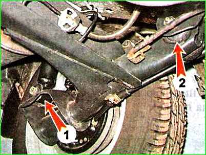
4. Visually check the condition of the rubber-metal hinges for attaching the shock absorbers 1 and the arms of the rear axle beam 2.
Hinges with one-sided bulging of rubber, tears and cracks are replaced.
Check the tightness of the nuts securing the suspension parts and tighten them if necessary.
Tightening torques for threaded connections of the rear suspension
Name of components and parts - Thread - Tightening torque Nm (kgcm)
- Wheel mounting bolts M12x1.25 - 65.2-92.6 (6.7-9.5)
- Rear wheel hub bearing nut M20x1.5 - 186.3-225.6 (19.0-23.0)
- Nut of the bolt for the lower shock absorber mounting to the rear suspension arm M12x1.25 - 66.6-82.3 (6.8-8.4)
- Nut securing the rear suspension shock absorber rod to the body M10x1.25 - 50.0-61.7 (5.1-6.3)
- Nuts of bolts securing the rear suspension arm to the bracket M12x1.25 - 66.6-82.3 (6.8-8.4)
- Nuts securing the rear suspension arm bracket to the body M10x1.25 - 27.4-34.0 (2.8-3.5)
- Inspect the suspension parts. Deformation and fatigue cracks in suspension parts are not allowed.
- We replace damaged parts.
- Replace springs, like shock absorbers, in pairs.


