Removing the front wheel drives
We carry out the work on an inspection ditch or overpass
Drain the oil from the gearbox.
Unscrew the front wheel hub bearing nut on the side of the drive being removed.
Unscrew the two bolts securing the ball joint.
Hang out the front of the car and remove the wheel.
To remove the right drive, remove the lower cover of the clutch housing.
You will need an assistant when removing the right drive.
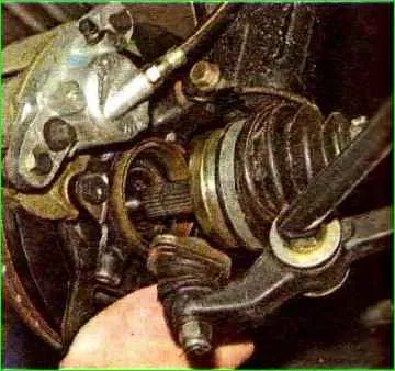
Move the steering knuckle with the stand to the side and remove the splined shank of the outer hinge housing from the hub.
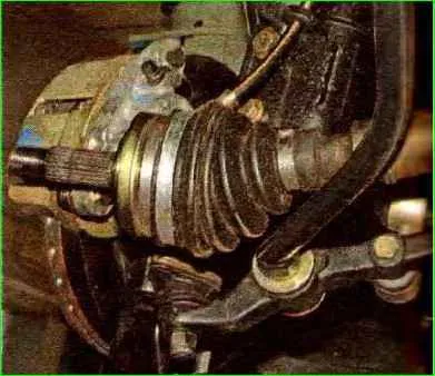
Place the drive on a stretcher.
Insert a chisel (preferably not sharpened) into the hole made in the bracket of the rear support of the power unit, so that the wedge of its working part hits the beveled surface of the internal joint housing.
To do this, you can turn the drive by hand.
From the flywheel side, place the mounting blade under the housing of the internal drive joint.
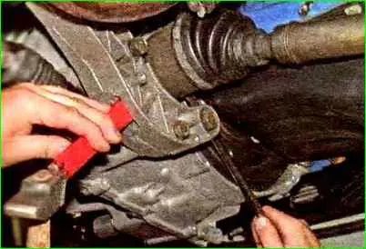
Using a hammer, hitting a chisel, and squeezing the inner joint body away from the gearbox with a mounting blade, we push the shank of the joint body out of the spline hole of the drive gear.
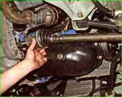
Remove the right drive.
When removing both drives, after dismantling the first one, it is necessary to insert a retainer into the hole of the drive gear, for example, a roller made of wood or soft metal, or an old internal CV joint.
Otherwise, the differential drive gears may become misaligned and the drives may not be able to be installed.
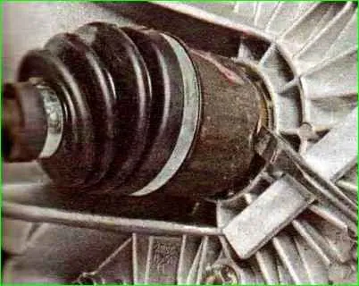
When dismantling the left drive, it is convenient to rest the mounting blade through the spacer on the gearbox housing
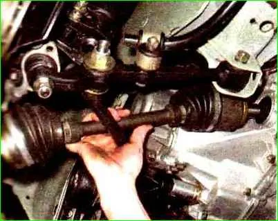
Remove the left drive
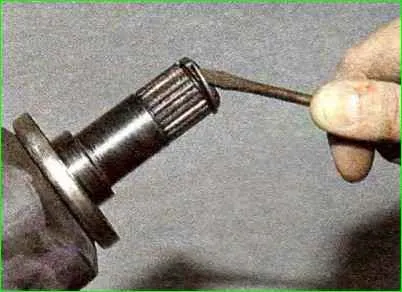
Before installing the drive, use a screwdriver to pry up the retaining ring of the shank of the internal joint housing, which secures the drive in the gearbox.
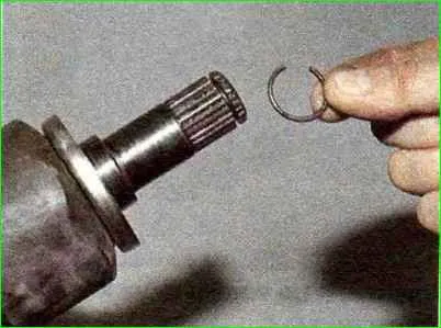
Remove the locking ring
Install a new ring into the groove of the shank of the internal joint housing.
Reuse of circlips is not permitted.
Insert the splined shank of the outer joint housing into the hole in the wheel hub, install the washer and tighten (without tightening) the hub bearing nut.
Then we insert the shank of the internal joint housing through the hole in the drive oil seal and, turning the shaft, align the splines of the shank with the splines of the drive gear.
By moving the suspension arm down, with a sharp movement of the rack with the steering knuckle towards the gearbox, we send the drive to its place.
By pulling the internal joint housing towards you or prying it with a mounting blade, we make sure that the housing shank is fixed in the drive gear.
We carry out further assembly in reverse order.
Removing the outer joint
We carry out the work when replacing the hinge or its cover. Remove the front wheel drive.
Clean the outside of the hinge and clamp the shaft in a vice with soft metal jaw linings.
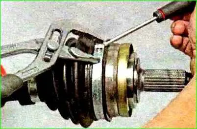
Squeezing the large clamp by the protrusions with sliding pliers and prying the end of the clamp with a screwdriver.
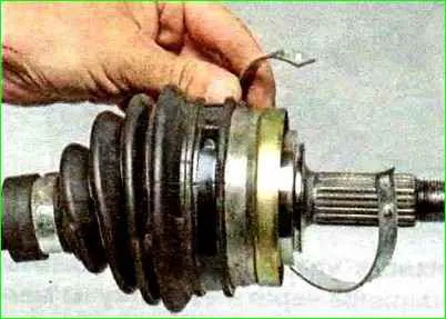
Disconnect and remove the clamp
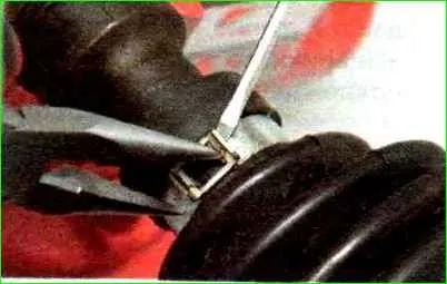
Use a screwdriver to bend the ends of the small clamp, squeeze them with pliers and pry the lock with a screwdriver.
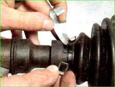
Remove the lock and clamp.
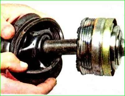
Pull the cover off the hinge body and turn the cover inside out.
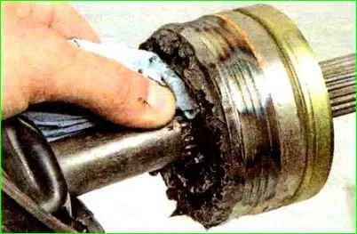
Use a rag to remove grease from the end of the hinge.
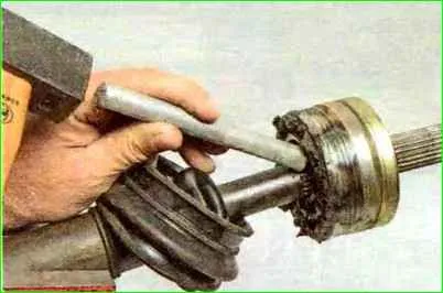
By striking the end of the hinge cage through a soft metal drift, we knock down the hinge.
The drift should not transfer force to the cage and balls to avoid damage.
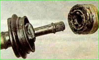
Remove the hinge.
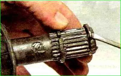
Pry up the retaining ring with a screwdriver
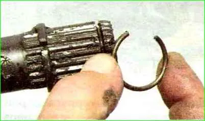
Remove the locking ring.
The thrust ring, which limits the movement of the hinge to the middle of the shaft, is removed only if it is replaced.
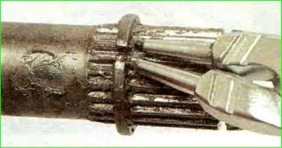
Unclench the thrust ring with pliers and remove it
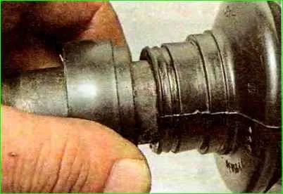
Slide the valve casing along the shaft
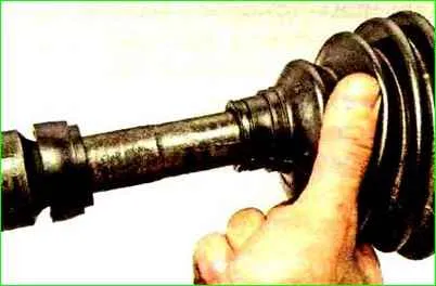
Remove the hinge cover.
To replace the valve casing.
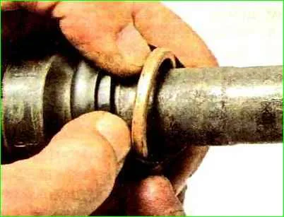
Unscrew the casing and remove the valve ring from it
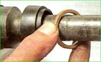
Remove the valve ring from the shaft.
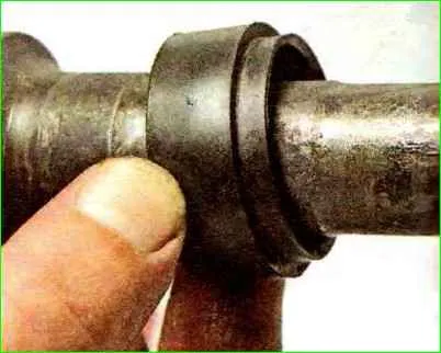
Remove the valve casing
Secure the hinge cover with new clamps.
Removing the inner hinge
We carry out work when replacing a hinge or its cover.
Remove the front wheel drive.
Clean the outside of the hinge and clamp the shaft in a vice with soft pads.
Having removed the clamps, remove the cover from the internal joint body and slide the cover along the shaft.
Move the hinge (outward) along the shaft until it stops.
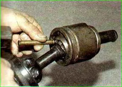
By striking the end of the hinge cage through a soft metal drift, we knock down the hinge.
The drift should not transmit force to the separator and balls in order to avoid them damage.
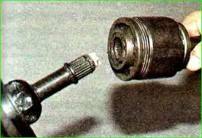
Remove the hinge.
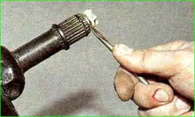
Pry up the plastic stop with a screwdriver
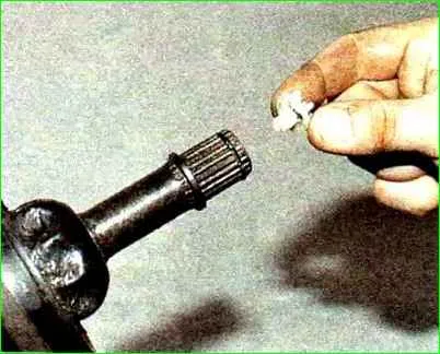
Remove the plastic stop.
Using a screwdriver, remove the retaining ring from the shaft groove.
Remove the cover, casing and valve ring.
To remove old grease from the hinge when replacing the cover, mark the relative positions of the body, race and hinge separator so that when assembling the drive they take their original places.
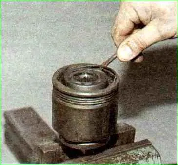
Use a screwdriver to pry up the inner hinge clamp
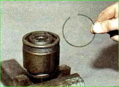
Remove the latch
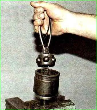
Take out the separator with the cage and balls.
Further disassembly of the hinge is not recommended. We remove the old grease from the hinge and wash it in kerosene.
Wipe the hinge with a rag and blow it with compressed air.
Inspect the balls, separator, cage and internal cavity of the body.
Balls, dents, cracks, and traces of corrosion are not allowed, such a hinge is replaceable.
Insert 80 g of CV joint grease (new or cleaned old) into the cavity of the hinge (new or cleaned old) and insert the separator with a cage and balls.
Install the retainer into the hinge body.
We clean the shaft of old grease and apply a thin layer of new grease to it.
We put the casing and valve ring and the hinge cover on the shaft.
We install a new retaining ring on the shaft and press the hinge onto the shaft through a wooden block.
We make sure that the hinge is securely fixed with the locking ring.
We put the cover on the hinge body, install the ring and valve casing on the cover, and secure the cover with clamps.


