The crankshaft position sensor is designed to generate signals by which the ECU synchronizes its operation with the engine operating cycle
Therefore, this sensor is often called a synchronization sensor.
The operation of the sensor is based on the principle of induction - when the crankshaft pulley teeth pass the sensor core, AC voltage pulses appear in the sensor circuit.
The frequency of pulses corresponds to the crankshaft rotation speed.
The teeth are located around the circumference of the pulley (every 6°). Two of them are separated from each other at an angular distance of 18°.
This was done to form reference signals in the sensor circuit - unique reference points, relative to which the ECU determines the position of the crankshaft - top dead centers in the first - fourth and second - third cylinders.
Engine operation with a faulty crankshaft position sensor is impossible.
The crankshaft position sensor cannot be repaired; in the event of a malfunction, it is replaced as an assembly.
Removing and installing the crankshaft position sensor
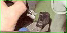
Press the plastic latch securing the wiring harness block with a screwdriver or your finger and disconnect the block from the sensor.
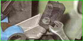
Unscrew the sensor mounting bolt with a 10 mm wrench
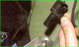
Remove the sensor from the cover boss
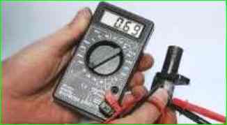
Check the sensor resistance. For a working sensor it should be 0.55 - 0.75 kOhm.
Install the crankshaft position sensor in the reverse order of removal.
Using a set of feeler gauges, we check the gap between the end of the sensor and the teeth of the crankshaft pulley.
The gap should be 1± 0.41 mm; it is specified by the design of the sensor and is not adjustable.
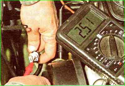
With the ignition off, disconnect the engine management system wiring harness block from the crankshaft position sensor.
Connect the tester probes to terminal “B” of the wiring harness block and engine ground.
With the ignition on and the crankshaft stationary, the tester should record a voltage of about 2.5 V.
The same voltage should be between terminal “A” of the wiring harness block and engine ground.
If the voltage values do not correspond to the norm, check the serviceability of the circuits (open and short to ground) between terminal “B” of the wiring harness block and terminal “34” of the controller, as well as between terminal “A” of the block and terminal “15” controller.
If the voltage values do not match and the circuits are working, the controller is faulty.
You can also check as follows:
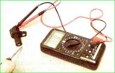
Connect a multimeter to the sensor terminals (in voltmeter mode with a measurement limit of up to 200 mV).
We quickly move the screwdriver blade close to the end of the sensor, and we observe voltage surges on the voltmeter.
The sensor can be checked more accurately by taking readings from it while it is installed on the engine and the crankshaft pulley is rotating.
For a working sensor, the voltage at the terminals reaches 0.3 V, replace the faulty sensor.


