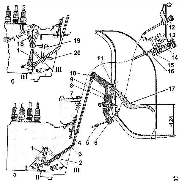
The figure shows the installation locations of the parts and their designations according to the spare parts catalog
We look at the figure and the table shows the decoding of the part.
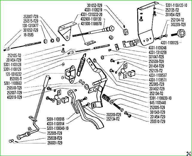
ZIL-5301 fuel supply control drive parts according to the catalog
- 120-1310232 Return spring
- 130-1310477 Radiator shutter rod sheath bushing
- 16-0685 Clamp of the conductor of the manual accelerator control rod cable
- 201452-П29 Bolt
- 201454-П29 Bolt
- 250508-П29 Nut
- 250510-П29 Nut
- 250515-П29 Nut
- 252005-П29 Washer
- 252007-П29 Washer
- 252134-П2 Spring Washer
- 252135-П2 Spring Washer
- 258038-П29 Cotter Pin
- 260031-П29 Pin
- 301047-П29 Bolt
- 301052-П29 Bolt
- 301543-П29 Bolt
- 302209-П29 Screw
- 402019-П29 Screw
- 431900-11080670 Eye springs
- 432900-1108130 Manual engine stop rod assembly
- 4331-1108014 Accelerator pedal
- 4331-1108125 Rod handle assembly
- 4331-1108219 Accelerator manual rod coupling
- 4331-1108248 Accelerator manual rod mounting bracket assembly
- 4331-1108571 Accelerator shaft mounting bracket
- 4331-1108587 Accelerator shaft bushing
- 4331-1310232-20 Bracket for mounting the blind drive
- 4331-1310259 Clamp for the rod housing
- 5301-1108016 Pedal foot
- 5301-1108030-10 Accelerator shaft assembly
- 5301-1108040-10 Intermediate accelerator rod assembly
- 5301-1108122-10 Rod mounting bracket
- 5301-1108128 Accelerator manual control rod
- 5301-1108129 Rod housing
- 5301-1108663 Seal
- 645.1005446 Spring
- 853995-П Paper clip