Pneumatic Brake System Overview
The pneumatic system of bus brakes consists of a compressor, pneumatic devices and pipelines. The diagram of the pneumatic drive of the brake system is shown in Figure 1.
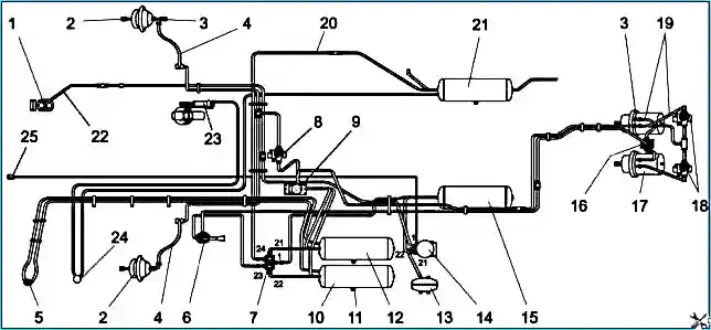
1 — compressor; 2 — front brake chamber; 3 — control valve; 4, 19, 22 — brake hoses; 5 — pressure gauge; 6 — parking brake valve;
7 — four-circuit safety valve; 8, 18 — ABS modulator; 9 — two-section brake valve; 10 — front circuit cylinder; 11 — condensate drain valve;
12 — rear circuit cylinder; 13 — regeneration cylinder of desiccant; 14 — dryer with pressure regulator; 15 — condensation cylinder; 16 — quick release valve;
17 — brake chamber with energy accumulator; 20 — pipeline to the door drive cylinder; 21 — door cylinder; 23 — pneumatic engine brake cylinder*;
24 — engine brake valve*; 25 — control valve; (*) — installed upon request
In order to prevent failures of the pneumatic devices of the brake system from clogging during the initial period of operation, strainers can be installed at the inlet of the brake valve, dryer, four-circuit safety valve and modulators.
Compressor
PAZ-32053-07: uses a single-cylinder piston-type air-cooled compressor. The compressor is driven by the drive gear of the high pressure fuel pump.
PAZ-4234: can use both a two-cylinder and a single-cylinder compressor. In both cases, the compressor has an air-cooled cylinder block and a water-cooled cylinder head. The drive is belt-driven from the crankshaft pulley.
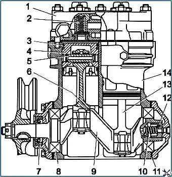
1 — cylinder head; 2 — discharge valve spring; 3 — piston ring; 4 — piston; 5 — piston pin; 6 — bearing liner; 7 — sealing ring; 8 — bearing; 9 — crankshaft; 10 — spring; 11 — gasket; 12 — seal; 13 — connecting rod; 14 — cylinder block
Compressor lubrication: Oil from the engine lubrication system is supplied through a hose to the compressor crankshaft channel and to the connecting rod bearings. Ball bearings, piston pins and cylinder walls are splash lubricated. Oil from the compressor is drained into the engine oil sump.
Signs of compressor malfunction:
- noise and knocking;
- excessive heating (more than 190°C);
- increased oil content in the condensate drained from the air cylinders.
Compressor maintenance: Once a year during seasonal maintenance, but not more than after 100,000 km, clean the compressor pistons and valves from carbon deposits.
Attention! Air leaks in the pneumatic brake system increase the duration of operation of the compressor under load and thereby reduce its service life.
Air Dryer with Pressure Regulator
Purpose: Cleaning compressed air from moisture and contaminants, automatically maintaining operating pressure in the pneumatic brake drive system.
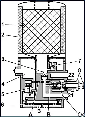
1 — drying agent; 2 — ring filter; 3 — check valve; 4 — moisture separation chamber; 5 — unloading valve; 6 — noise muffler; 7 — ventilation hole; 8 — adjusting screws; 9 — inlet valve.
Ports: 1 — from compressor; 21 — to four-circuit safety valve; 22 — to regeneration air receiver; 3 — atmospheric outlet
Electric heating: The air dryer has an electrically heated valve assembly, which is turned on when the key in the instrument switch is turned to position "I". Electric heating turns on automatically at ambient temperatures below +10°C and turns off after heating to +30°C.
Dryer operation check: Daily check for the absence of condensation in the cylinder located after the dryer. If condensation appears in the receivers, replace the filter element. If oil is present in the condensate, repair the compressor.
Attention! To prevent brake system failures, the air dryer filter cartridge should be replaced once a year regardless of its condition before the start of the winter operation period.
Replacing the air dryer filter element:
- Clean the surface of the dryer from dirt.
- Loosen the threaded connection of the discharge pipe from the compressor and bleed air from it.
- Unscrew the filter element cartridge by rotating counterclockwise.
- Install a new cartridge, lightly lubricating the sealing gasket with oil.
- Tighten the cartridge by hand to a torque of no more than 15 N·m.
- Tighten the threaded connection of the discharge pipe.
Four-Circuit Safety Valve
Purpose: Dividing the supply line into two main and two additional circuits, automatically turning off one of the circuits in case of damage and preserving the compressed air supply in undamaged circuits, as well as preserving air in all circuits in case of damage to the supply line.
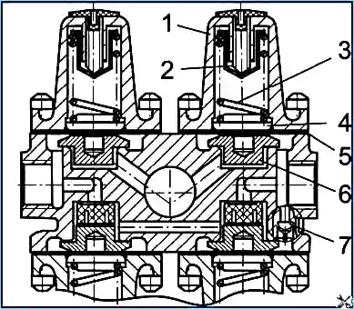
1 — cover; 2 — adjusting screw; 3 — spring; 4 — spring guide; 5 — diaphragm; 6 — valve; 7 — bypass valve
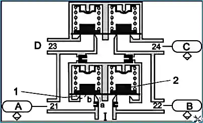
1 — inlet; 1, 2 — bypass valves; 21, 22 — service brake system circuits; 23 — parking brake circuit; 24 — door drive circuit.
Receivers: A, B — service brake system circuit receivers; C — door drive receiver; D — parking brake circuit receiver
Safety valve section adjustment: First, the main valves of the service brake system and door drive (sections 21, 22, 24) open at a bypass pressure of (607–637) kPa, then the parking brake system valve (section 23) opens at a bypass pressure of (656–686) kPa.
Parking Brake Valve
Purpose: Control of the spring energy accumulators of the parking brake system. When the bus is moving, the valve handle is in the extreme forward position. To release the brakes, pull the handle in the radial direction — it freely returns to the "released" position. In the extreme rear position, the handle is locked.
Quick Release Valve
Purpose: Accelerating the release of air from the actuators by reducing the path traveled by compressed air during release.
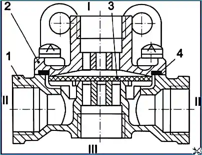
1 — body; 2 — cover; 3 — diaphragm; 4 — sealing ring; I, II, III — ports
Two-Section Brake Valve
Purpose: Control of wheel brake mechanisms with a dual-circuit brake drive. Ports "A" and "B" are connected to the air receivers of two separate circuits. Compressed air flows from ports "G" and "D" to the brake chambers. Port "C" is atmospheric.
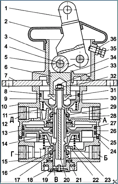
1 — lever; 2 — protective boot; 3 — lever body; 4 — roller axis; 5 — roller; 6 — pusher; 7 — support plate; 8, 14, 24, 25, 26, 27 — sealing rings;
9 — follower piston; 10 — upper body; 11, 23 — piston spring; 12, 21 — valve spring plate; 13 — large piston; 15 — lower body; 16 — lower section valve;
17, 28 — valve spring; 18 — atmospheric valve body; 19 — atmospheric valve; 20 — pusher; 22 — small piston; 29 — upper section valve; 30 — elastic element;
31 — plate; 32 — nut; 33 — stud; 34 — bushing; 35 — lever stop bolt; 36 — lock nut; A, B, C, D, E — ports
Brake valve maintenance:
- Check the valve mounting and the integrity of the protective boot.
- Diagnostic check of correct valve operation.
- It is recommended to perform preventive disassembly of the valve once every 2 years for cleaning, lubrication and replacement of sealing rings.
Attention! In winter, if the valve freezes, it is not recommended to thaw the valve with an open flame. Use warm air or hot water.
Assembling and Checking Brake Valve Functionality
Assembly requirements:
- Assembly must be performed under conditions that prevent abrasive dust from entering.
- Rubber parts must be assembled carefully to avoid damage.
- All rubbing surfaces of parts should be lubricated with a thin layer of CIATIM 221 lubricant (AZMOL ZhT-72 is permitted).
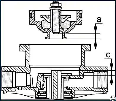
1 — lock nut; 2 — adjusting bolt; 3 — shell; 4 — roller; 5 — pusher
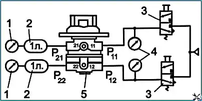
1, 4, 5, 9 — pressure gauges; 2, 8 — air cylinders; 3, 6 — valves; 7 — brake valve; 11, 12 — compressed air supplies; 21, 22 — compressed air outlets;
P11, P12 — inlet pressure; P21, P22 — outlet pressure
Brake valve drive adjustment: The total brake pedal travel (movement of the pedal pad center) should be 105–117 mm, free play — 18–25 mm.
To adjust the drive: rotate the fork along the rod thread to align the fork hole with the valve lever hole, unscrew the fork one turn, install the pin, cotter pin it, and tighten the lock nut.
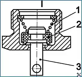
Control Outlet Valve
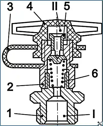
1 — fitting; 2 — body; 3 — loop; 4 — cap; 5 — pusher with valve; 6 — spring; I, II — ports
Condensate Drain Valve
1 — spring; 2 — valve; 3 — pusher; I — port
Brake Chambers
Brake chambers are designed to actuate the wheel brake mechanisms. The brake chamber with a spring energy accumulator is designed to actuate the rear axle brake mechanisms when the service or parking brake systems are engaged.
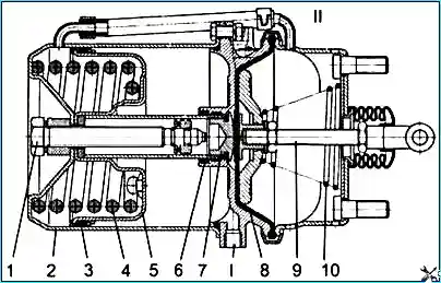
1 — screw; 2 — cylinder; 3 — seal; 4 — spring; 5 — piston; 6 — sealing ring; 7 — pusher; 8 — diaphragm; 9 — rod; 10 — return spring;
I — compressed air supply to working chamber; II — supply to spring energy accumulator
Attention!
- Before releasing the brakes, secure the bus against rolling away.
- Do not disassemble the energy accumulator without using a special tool, as a powerful spring is inside it in a compressed state.
- Before operating the bus, bring the energy accumulators of the brake chambers into working condition: fill the brake system with air, set the parking brake valve handle to the release position, and tighten screw 1 all the way.
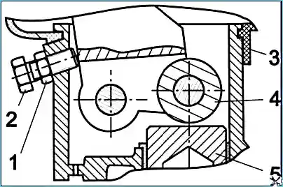
Auxiliary Brake System (Engine Brake)
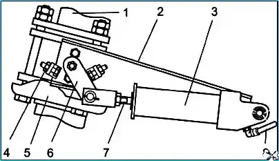
1 — engine exhaust pipe; 2 — pneumatic cylinder bracket; 3 — pneumatic cylinder; 4 — lever travel limiter; 5 — engine brake housing;
6 — engine brake flap lever; 7 — pneumatic cylinder rod; 8 — pipeline to control valve
Attention! Rules for using the engine brake:
- Before applying the engine brake, release the fuel control pedal.
- The engine brake only slows down the movement, preventing the bus from gaining speed on long descents. It is not intended for stopping the bus, cannot be used for emergency braking or as a parking brake.
- The engine brake is used only when driving on long descents with a gear engaged. Select a gear where the engine speed does not exceed the maximum permissible (2400 rpm).
Pneumatic Brake System Maintenance
Tightness check:
- With the brake pedal pressed, the pressure drop should not exceed 0.05 MPa (0.5 kgf/cm²) for 15 minutes.
- With the controls in the free position — 0.05 MPa for 30 minutes.
Maintenance recommendations:
- The tightening torque of fittings, plugs, and nuts should not exceed 30–50 N·m.
- Once every two years, it is recommended to perform preventive disassembly of the brake valve, brake chambers, safety valve, hand brake valve, quick release valve, and replace the dryer cartridge regardless of their technical condition.
- Detected faulty devices must be repaired using repair kits and checked for functionality.
Attention! Pipeline sagging, contact with moving and heating parts, and bending of pipelines with a decrease in their flow area are not permitted.
")

")
")
")
")
")
")
")