The diesel power system, in accordance with the diesel engine configuration, consists of:
- - Common RAIL accumulator injection system, including a fuel pump,
increasing gearbox of the injection pump drive, injectors, high-pressure fuel accumulator, speed sensors (crankshaft and input shaft of the injection pump drive gearbox), sensors for the state of the working environment (pressure and temperature of fuel and air), electromagnetic actuators (fuel pressure regulator , injector solenoid valves), electronic control unit;
- low pressure fuel lines;
- high pressure fuel lines; intake manifold; exhaust manifold;
- turbocharger;
fine fuel filter; fuel pre-filter, air cleaner, fuel tank, charge air cooler, muffler.
The diagram of the diesel power system indicates a means of facilitating diesel starting at low ambient temperatures - a glow plug.
The diagram of the diesel power supply system is shown in Figure 1.
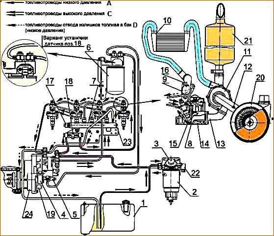
1 - fuel tank; 2 - fuel pre-filter; 3 - manual fuel priming pump; 4 - high pressure fuel pump; 5 - electromagnetic pressure regulator; 6 - fine fuel filter; 7 - high pressure fuel accumulator; 8 - nozzle; 9 - intake manifold; 10 - charge air cooler; 11 - turbocharger; 12 - air filter clogging sensor; 13 - exhaust manifold; 14 - cylinder head; 15 - glow plug; 16 - charge air temperature and pressure sensor; 17 - high fuel pressure sensor; 18 - fuel temperature and pressure sensor; 19 - camshaft speed sensor; 20 - air cleaner; 21 - muffler: 22 - fuel heater; 23 - pressure limitation valve; 24 - fuel injection pump drive gearbox; A - low pressure fuel lines; C - high pressure fuel lines; D - pipelines for discharging fuel into the tank
The circuit diagram of the COMMON RAIL power supply system is shown in Figure 2.
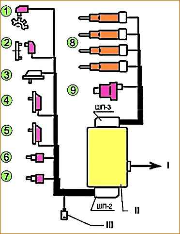
Location of sensors and actuators in Figure 2 and in the table.
Power to the electronic unit for monitoring, control and communication circuits must be supplied directly from the battery terminals.
The crankshaft frequency sensor is installed on the timing cover
The speed sensor of the input shaft of the injection pump drive gearbox is installed on the gearbox housing of the high pressure fuel pump
The fuel temperature and pressure sensor is installed on the fuel line route from the booster pump to the fine fuel filter or in the housing of the fine fuel filter
Oil temperature and pressure sensor installed in the cylinder block
The charge air temperature and pressure sensor is installed in the intake manifold
The high fuel pressure sensor is installed in the fuel rail
The coolant temperature sensor is installed in the thermostat housing
The pressure regulator is installed in the high pressure fuel pump

")
")
")
")
")