Maintenance of the fuel filter-sump
Periodically drain the dirt and water through the drain hole (Fig. 1)
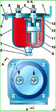
Before the winter season of operation, remove and wash the filter element in gasoline or acetone without disassembling it.
After washing, blow the filter element with air under a pressure of no more than 97.5 kPa (1 kgf/cm 2) so as not to damage the filter plates.
Fuel pump maintenance
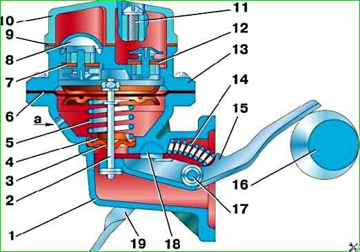
Periodically remove dirt from the head 13 (Fig. 2) of the fuel pump housing and wash the strainer 8.
When installing cover 10 in place, make sure that gasket 9 is intact.
Fuel leakage through the inspection hole indicates a malfunction of diaphragm 6. In this case, remove the pump, disassemble and replace the diaphragm.
When assembling the pump, tighten the head mounting screws with the diaphragm pulled to its lowest position.
Periodically check the fastening of the pump to the engine and the tightness of the fuel line connections.
Before the onset of the hot season, check the pressure developed by the pump.
Check without removing the pump from the vehicle with the engine running at low crankshaft speed and idling.
During the test, disconnect the tube supplying fuel to the carburetor from it and connect it to a pressure gauge with a scale of up to 100 kPa (1 kgf/cm 2).
The engine is started and powered using the fuel available in the carburetor float chamber. The pump must create a pressure of at least 11.7 kPa (0.12 kgf/cm 2).
After stopping the engine, the pressure indicated by the pressure gauge should not drop within 10 s.
If the pump does not meet the specified requirements, repair or replace it.
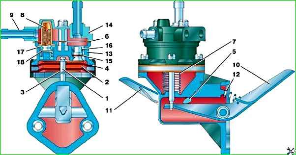
In Fig. Figure 3 shows the fuel pump 2105–1106010–50 installed on vehicle parts. Its maintenance is similar to that described above.
The fine fuel filter can be used in two types: collapsible, with a replaceable filter element, and non-removable.
The dismountable fuel filter is mounted on the cylinder head bracket.
It consists of a housing, a rubber gasket, a rubber sealing bushing, a ceramic or paper filter element, a spring, a plastic settling cup and mounting parts for the settling cup.
A filter with a plastic non-separable housing and a paper filter element is installed on the hose supplying fuel to the carburetor.
Maintenance of the fine fuel filter
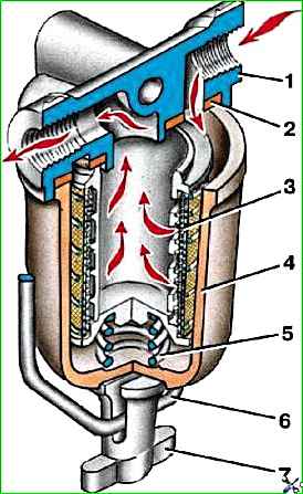
Periodically disassemble it to wash the sump and filter element.
To disassemble, loosen the wing nut 7 (Fig. 4) and move the bracket 6 to the side, then remove the sump together with the filter element 3.

")
")
")
")
")