The tanks are attached to the frame side members from the outside using brackets and clamps. Cardboard spacers are placed between the clamps and the tank
The tanks are connected by fuel lines to a switch valve installed under the driver's seat. With its help, you can switch the fuel intake from one tank to another.
The capacity of one tank is 39 liters.
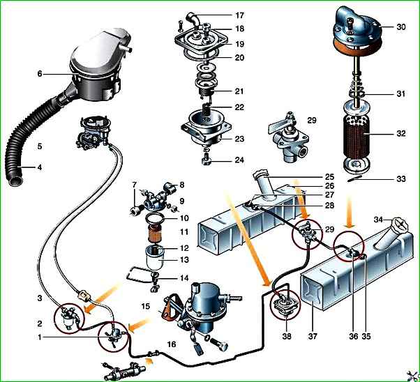
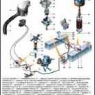
Power system: 1 - fuel pump; 2 * - fine fuel filter with a replaceable filter element; 3 * - fine fuel filter (non-separable); 4 - air intake hose; 5 - carburetor; 6 - air filter; 7, 8 - fittings; 9 - cover; 10 - gasket; 11 - filter element; 12 - spring; 13 - settling glass; 14 - settling cup holder; 15 - fuel pump gasket; 16 - lever for manual drive of the fuel pump; 17,18 - fittings; 19 - cover; 20 - gasket; 21 - filter element; 22 - spring; 23 - filter housing; 24 - threaded drain plug; 25 - filler neck; 26 - left fuel tank; 27, 35 - fuel level indicator sensors; 28, 36 - fuel intakes; 29 - fuel tank switching valve; 30 - cover; 31 - spring; 32 - mesh filter; 33 - locking pin; 34 - filler plug; 37 - right fuel tank; 38 - settling filter; * It is possible to install a dismountable or non-separable fine fuel filter.
At the top of each tank there is a fuel intake, consisting of a tube and a filter in the form of a brass mesh, as well as an electric fuel level indicator sensor.
In some modifications, there is a drain hole with a threaded plug at the bottom of the tank.
The plastic threaded neck plug has inlet and outlet valves to prevent the formation of vacuum and increased pressure inside the tank.
On some vehicles, the fuel tank filler neck is equipped with a retractable pipe for easy refueling.
The fuel tank filler flap is closed with a lid on the outside.
Fuel lines are made of rubber hoses and copper pipes.
The hoses are connected to the fuel pump, fuel tank switch valve, and sediment filter through fittings with union nuts.
On the pipes of the fuel intakes, carburetor and fine fuel filter, the hoses are secured with clamps.
The copper tube is connected to the settling filter at one end through a fitting, and at the other end it is inserted into a rubber hose and tightened with a clamp.
Maintenance of fuel tanks involves periodically draining sediment and water from them, washing the removable filters of the fuel receiving pipes and the tanks themselves.
Periodically check that the tanks are securely fastened and, if necessary, tighten their mounting bolts.
To wash the fuel tanks, remove them from the vehicle.
Before removing the tank from the vehicle, do the following:
- – disconnect the battery;
- – open the hatch in the body floor above the fuel level indicator sensor and the fuel receiving pipe;
- – disconnect the wire from the fuel level indicator sensor and insulate it;
- – disconnect the fuel line pipe from the receiving pipe flange.
Then unscrew the bolts of the tie clamps and bend the clamps down so that they do not interfere with the lowering of the tank.
Remove the tank, wash it and the receiving tube filter with clean gasoline or hot water and blow with compressed air.
The filter of the receiving tube can be washed without removing the tank from the car; in this case, remove the tube with the filter through the hatch in the floor of the body.
Maintaining the fuel tank cap
Keep the fuel tank cap clean and make sure that the vent hole in the center of the cap is not clogged with dirt; if necessary, clean it.
For normal operation of the power system in high-temperature conditions, timely operation of the plug valves is important. Therefore, before the onset of the hot season, check their operation.
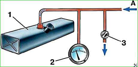
To determine when the exhaust valve operates, connect as shown in Fig. 1 diagram of the fuel tank to the compressor, open tap 3 and turn on the compressor.
Then, smoothly closing the tap, increase the pressure in the tank and monitor the readings of micromanometer 2.
At the moment the release valve is activated, the pressure in the tank should drop.
To check the operation of the intake valve, connect the fuel tank in the same way to the vacuum pump.
The further verification procedure is similar to that described above.
If the outlet valve opens at a pressure of less than 0.78 kPa (0.008 kgf/cm 2) and more than 4.9 kPa (0.05 kgf/cm 2) or the intake opens at a vacuum of more than 2.7 kPa (0.03 kgf/cm 2), then replace the plug.

")
")
")
")
")