Disassemble the transfer case in the following order:
- Unscrew the nuts and bolts securing the transfer case to the gearbox and disconnect the components.
- Remove the gearbox intermediate shaft thrust ring from its socket.
- Remove the gaskets from the mating ends.
- Remove the power take-off hatch.
- Remove the cover of the switching mechanism with rods and levers.
- Remove the screws and remove the parking brake drum.
- Unscrew the rear axle drive shaft flange nut and remove the flange.
- Unscrew the bolts securing the brake mechanism to the transfer case and remove it.
- Remove the flange from the front axle drive shaft and the front bearing cover of this shaft with a cuff.
- Unscrew the bolts connecting the crankcase parts and disconnect the crankcase so that all internal parts remain on the cover. Do not remove the plugs and bearing cup unless absolutely necessary.
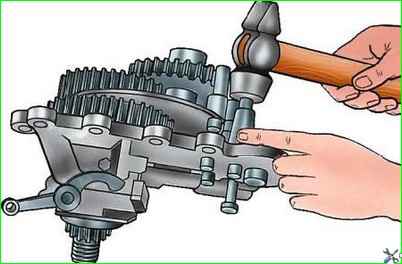
- Remove the shift rod locking plate and knock out the shift rods (Fig. 2) with a copper hammer, while simultaneously removing the shift forks from them.
- At the same time, keep the balls and springs of the clamps located in the fork sockets from falling out.
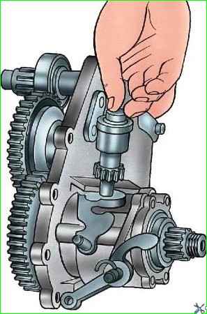
Remove the stopper of the driven gear fitting (Fig. 3) of the speedometer and remove the gear together with the fitting.
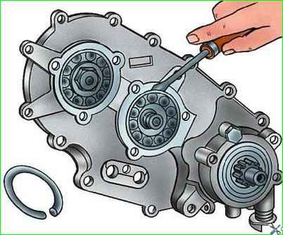
- Remove the bearing caps for the intermediate shaft and the front axle drive shaft.
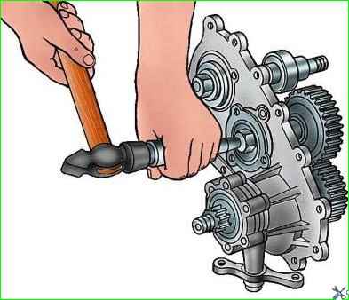
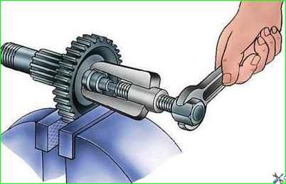
- Remove the retaining rings (Fig. 4) of the bearings and knock out the shafts (Fig. 5)
- Remove the bearings (Fig. 6) from the shafts with a puller.
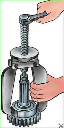
Press out the rear axle drive shaft. Remove the oil deflector, the speedometer drive gear and remove the bearing with a puller.
Remove the rear bearing cover of the rear axle drive shaft and remove the bearing.
- * Unscrew the nut of the lever axles, press out and remove the levers.
- * Remove the arm bracket.
- * On vehicles of the UAZ-3741 family, instead of working according to paragraphs 15, 16, it is necessary to remove the control shafts
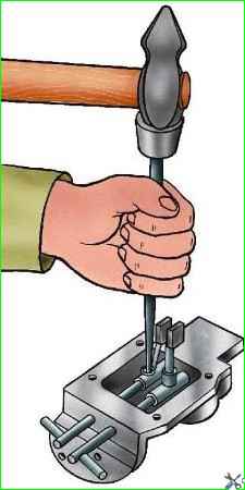
- Knock out the five plugs from the switch mechanism cover.
- Knock out the pins (Fig. 7) from the levers towards the removed plugs.
Remove the front axle control rod, the lock ball through the side hole, and the forward and downshift control rod.
Until March 1993, the inner ring of the roller bearing was pressed onto the intermediate shaft of the transfer case (Fig. 8), and until July 1994, a shaft fastening nut was installed
Assessment of the technical condition of parts
After disassembling, thoroughly rinse all parts of the transfer case in kerosene, blow with compressed air and inspect. Please note the following:
Transfer case housing and its cover.
External inspection reveals cracks, chips, kinks, paying special attention to the crankcase and cover mounting ears, the condition of the threads in the holes, the absence of nicks and burrs on the sealing surfaces.
Replace the crankcase and cover that have cracks, chips, or breaks.
Remove minor defects. Please note that the crankcase and transfer case cover are machined together and are therefore not interchangeable between transfer cases.
Gears. The teeth should not be chipped ornick.
The side surface of the teeth should not have any signs of chipping or crushing, and there should be no burrs on the end surfaces of the gears.
The seating surfaces must not have any damage or wear that could interfere with the alignment of the parts. Replace worn gears.
The transfer case shafts must not have any damage to the threads. The shaft splines should not have burrs, burrs, nicks, or deep crushing of the side surfaces. Replace worn shafts.
The driveshaft flanges must not have a spline width greater than 4.645 mm.
Bearings must not have damage to cages, cracks and chips of rings, chipping of raceways, as well as noticeable radial and axial clearance.
Replace worn bearings.
The cuffs must not have ruptures, tears or cracks on the working surface or deformation of the reinforcement.
The wear strip of the working edge should not be more than 2 mm. Replace worn cuffs.
Shift forks should not be cracked, bent or excessively worn. Replace worn parts.
The shifting mechanism rods must have securely riveted pins.


