Restore the normal size of the gaps between the pads and brake drums and reduce the pedal stroke using eccentrics, in which the hexagonal heads of the axles are brought out through the shield
Adjust the gaps between the pads and brake drums (current adjustment) in the following order:
- 1. Jack up the wheel whose brake mechanism needs to be adjusted.
- 2. While rotating the wheel, gradually turn the adjusting eccentric until the wheel brakes.
- 3. Gradually release the eccentric, turning the wheel until it rotates freely without the drum hitting the pads.
- 4. Adjust the gaps between the pads and drums of the remaining brake mechanisms in the same way.
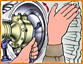
When adjusting the brake mechanisms of the front wheels and the front brake pads of the rear wheels, rotate the wheel forward (Fig. 1).
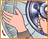
When adjusting the rear brake pads of the rear wheels, rotate the wheel back (Fig. 2).
To reduce the gaps, turn the eccentrics in the direction of rotation of the wheel, and to increase them, turn them against them.
5. Check while the car is moving that the brake drums do not heat up and that the brake mechanisms operate smoothly when braking.
During the current adjustment, do not use the support pins, as this will disrupt the factory settings of the pads.
When replacing friction linings, adjust the installation of the pads.
Adjust the brake mechanisms when the brake drums have completely cooled down and the wheel bearings are correctly adjusted.
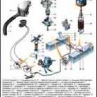
Adjust the free travel of the pedal on vehicles of the UAZ-31512 family by changing the position of the stop of switch 14 (see Fig. 3) of the brake signal.
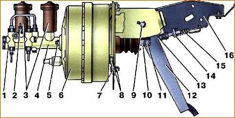
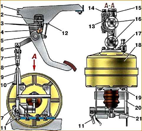
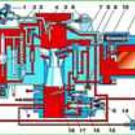
Adjust the free travel of the pedal on vehicles of the UAZ-3741 family by changing the length of the vertical rod 9 (see Fig. 4) using forks 7, having previously unscrewed the lock nuts 8.
Check the free play of the pedal when the engine is not running.
The free play of the pedal on UAZ vehicles is 5–14 mm, counting along its platform.

")
")
")
")
")