Gear divider for KamAZ vehicle
The gear divider is mechanical, accelerating, with a pneumatic gear shift drive and consists of a housing 14 cast integrally with the clutch housing, a primary shaft 1 and an intermediate shaft 15, one pair of gears, a synchronizer 8 and a gear shift mechanism.
Input shaft 1 is mounted on two ball bearings.
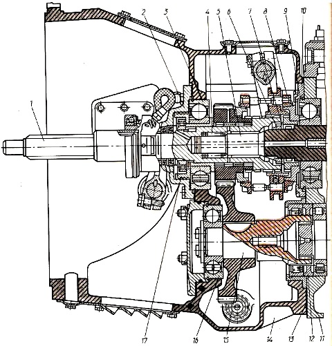
The front bearing of the input shaft with a sealing collar is installed in the bore of the crankshaft, and the rear bearing 3 is installed in the socket of the divider crankcase partition.
The rear bearing is secured against axial movements by a retaining ring.
The splined front part of the shaft meets the cylindrical journal under the front ball bearing.
The hubs of the driven clutch discs are installed on the shaft splines.
In the middle part the shaft has a cylindrical journal on which a gear and bearing 3 are mounted.
The bearing is mounted on a sleeve, which is fixed on the shaft together with the oil injection ring 17 with a threaded nut.
The oil injection ring supplies oil through the inclined holes of the input shaft into its cavity, from where it enters the channels of the primary and secondary shafts of the gearbox.
The axial stroke of the input shaft is regulated by a set of metal spacers installed between cover 2 and bearing 3.
At the rear end of the shaft, the involute splines are divided into three rims by two grooves.
The teeth of the outer rims are thinner than the teeth of the middle rim, which, in combination with the gear rims of the synchronizer carriage, creates a “lock” that prevents the gears in the divider from switching off automatically.
An inertial type finger synchronizer is movably mounted on the splines.
A helical drive gear with a cone designed for synchronizer operation rotates on two roller bearings.
The divider input shaft has an internal cylindrical cavity for installing the gearbox input shaft with the front roller bearing assembly.
Axial forces arising during operation of the gearbox are perceived by the rear bearing 3 of the input shaft.
The required oil level in the splitter housing is maintained by circulating it through two holes in the walls of the splitter housings and the main gearbox.
The intermediate shaft 15 of the divider is mounted on two supports: a ball bearing placed in the seat of the divider housing partition, and a roller bearing installed in a special seat fixed in the bore of the rear end of the divider housing.
The intermediate shafts of the divider and gearbox are coaxial due to the installation of a spacer sleeve 12, which simultaneously acts as a centering ring, and are connected to each other by splines.
The drive gear of the intermediate divider shaft is helical, pressed onto the shaft key onto the shaft until it stops at its end.
A ball bearing is installed on the front journal of the shaft. It is secured against axial movements on the shaft by a thrust washer screwed to the shaft with two bolts.
The outer bearing ring, placed in the housing of the crankcase bulkhead, is held against axial movements by a retaining ring installed in its groove.
The bearing is closed with a cover, in the groove of which a sealing ring is installed, and a sealing gasket is placed between the end of the cover and the partition. Axial forces are absorbed by the ball bearing.
To ensure smooth alignment of peripheral speeds and shock-free engagement of the high and low gears of the divider, an inertial-type synchronizer with conical friction rings is installed on the input shaft.
The divider synchronizer does not differ in operating principle from the main box synchronizers, but is structurally designed differently, their parts are not interchangeable, with the exception of springs and retainer balls.
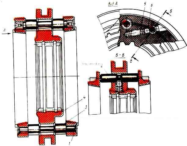
The divider synchronizer (Fig. 2) consists of a carriage 4, two identical friction rings 1, six locking fingers 3 and six locking fingers 2.
The synchronizer carriage 4 has a groove on the outer diameter into which the gear shift fork nuts fit.
The internal hole of the carriage is slotted, consisting of three toothed rims.
The outer gear rims have a thinner tooth thickness than the middle one, which, in combination with the gear rims of the primary shaft of the divider, protects the gears from self-switching off while the vehicle is moving.
The carriage has six holes around its circumference for the locking fingers, six holes for the locking fingers
The holes for the locking pins are chamfered on both sides with an angle equal to the angle of the chamfers of the locking pins.
Two identical friction rings 1 are pressed onto the outer ends of the locking fingers until they stop at their ends.
The fingers of 2 clamps are installed in the holes of the carriage between the friction rings.
In the middle part of the fingers there is a groove into which, when changing gears, a ball 6 enters, pressed by a spring 5 located in the blind hole of the carriage.
The operation of the synchronizer is similar to the operation of the synchronizer for the second and third gears of a five-speed gearbox.
The gear shift mechanism of the divider is designed to ensure that the required gear is engaged while the vehicle is moving and consists of a fork with nuts and a fork shaft, at the end of which a lever is installed.

The fork shaft is installed in the holes of the divider housing.
In the middle part, a fork with breadcrumbs is installed on the roller using a segment key.
The fork is secured with two coupling bolts.
To ensure installation and access to the switching mechanism, there is a hatch on the divider housing, closed with a lid.
At the outer end of the roller, a lever connected to the piston of the power cylinder is mounted on a segment key.
The lever is secured with a coupling bolt. Lever travel is limited by two adjustable stop bolts.
The low gear is engaged by moving the divider synchronizer carriage along the splines of its input shaft back until it is completely connected to the gear ring of the gearbox input shaft clutch.
In this case, the torque from the input shaft of the divider is transmitted to the input shaft of the gearbox, and then in the same way as in a five-speed gearbox (Fig. 3).
The top gear is engaged by moving the divider synchronizer carriage along the splines of its input shaft forward until it is completely connected to the ring gear of the divider input shaft gear.
The torque from the input shaft of the divider is transmitted through a gear interlocked with it to the drive gear of the intermediate shaft of the divider and then through a splined connection to the intermediate shaft of the gearbox.
In this case, when the gears in the main box are engaged, the torque in all gears decreases by 0.815 times, and the speed accordingly increases by approximately 1.22 times.

")
")
")
")
")