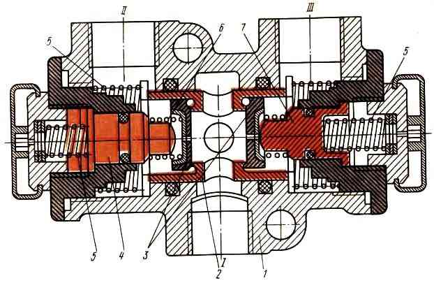
The double safety valve (Fig. 1) is designed to divide the supply line into two autonomous circuits (auxiliary and parking brake) and automatically turn off the damaged circuit in order to maintain the required pressure in the healthy circuit.
It consists of a housing 1, a central piston 2 with two check valves 3, two thrust pistons 4 and springs 5, 6, 7, respectively, thrust pistons, a central piston and check valves.
In the initial position before starting work (Fig. A), the central piston 2, under the action of springs 6, occupies the middle position.
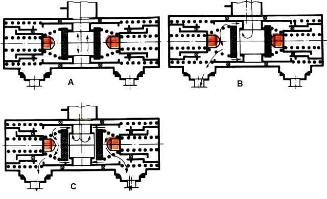
In the operating position (Fig. C), when air is supplied from the condensation receiver to inlet “I”, compressed air through the hole in piston 2 presses the check valves and flows to outputs “II” and “III”.
If one of the circuits is damaged (Fig. B), the pressure in it drops and the central piston 2, under the influence of the pressure difference, moves towards the damaged circuit, its seat rests against the check valve 3 and presses it against the piston 4, turning off the damaged circuit.
The check valve of the secondary circuit remains open, and compressed air from the supply line continues to flow into the undamaged circuit.
The double safety valve, if one circuit is faulty, maintains the compressed air pressure in good working order within the range of 520-540 kPa.
When the pressure at the valve inlet increases above 540 kPa, spring 5 is compressed under the action of compressed air acting on check valve 3, the valve is torn off the seat and excess compressed air is released into the damaged circuit.

")
")
")
")
")