The divider gear shift mechanism is controlled by a pneumomechanical system (Fig. 1), which consists of a pressure reducing valve 4, a divider control valve 3, a divider activation valve 1 and air ducts
Air from the pneumatic drive of the vehicle's brake system at a pressure of 620-750 kPa is supplied to the input of pressure reducing valve 4, at the outlet of which a constant pressure of 395-445 kPa is maintained.
The pressure is regulated by spacers installed on the spring housing.
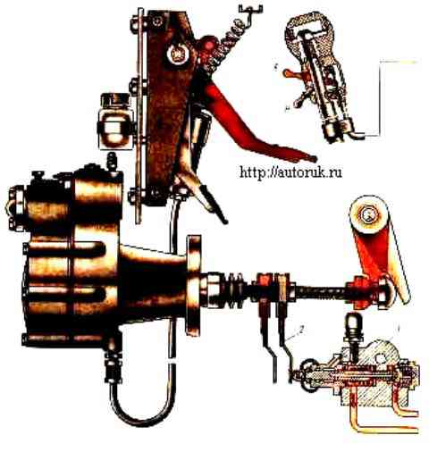
The divider control valve 3, depending on the position of the spool, directs the air coming from the pressure reducing valve into one of the cavities under the piston of the air distributor 6 and moves its spool to one of the two extreme positions, thus ensuring the supply of air to cavity “A” or "B" cylinder.
Preliminary selection of gear in the divider is made by moving the switch lever to the “B” or “H” position.
Air from pressure reducing valve 4 under the cylinder piston enters through valve 1, which opens at the end of the pusher stroke, i.e., when the clutch is completely disengaged, with stop 2 attached to the piston pusher of the clutch pneumatic booster.

In Fig. Switch 2 is in the low gear position, the valve stem 3 is in the upper position, and compressed air is supplied through the upper pipeline to the air distributor 6 and moves the spool all the way to the left, holding it in this position.
In this case, cavity “A” of the power cylinder communicates with the supply pipeline coming from valve 1 for switching on the divider, but compressed air does not flow there when the clutch is engaged.
To supply compressed air to cavity “A”, you need to press the clutch pedal.
In this case, the stop mounted on the clutch drive rod will move and press on the splitter valve rod.
Compressed air supplied to the switching valve from pressure reducing valve 4 will flow to the air distributor and then into cavity “A”.
In the above figure, compressed air enters cavity “A” of the power cylinder and does not move the piston from the extreme right position, keeping the gear shift lever in the same position and the low gear in the divider engaged.
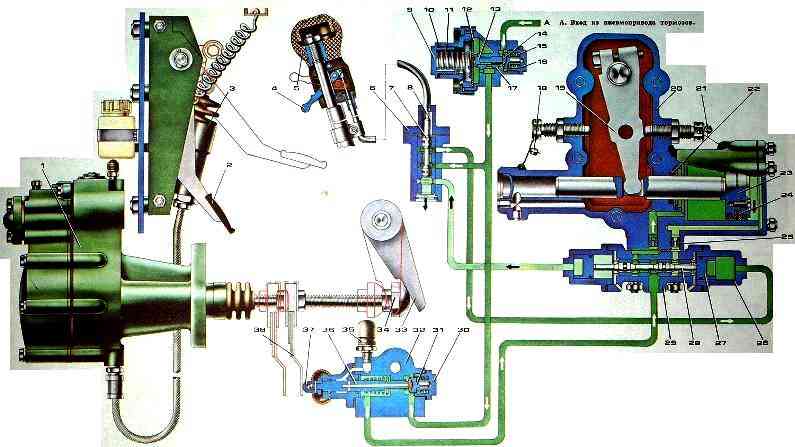
Divider control drive: 7 - pneumohydraulic clutch drive amplifier; 2 - clutch control pedal; 3 - main cylinder; 4 - gear divider control valve switch; 5 - gear shift lever handle; 6 - control valve; 7 - spool; 8 - crane cable; 9 - plug; 10 - adjusting shims; 11 - balancing spring; 12 - diaphragm; 13 - intake valve stem; 14 - inlet valve; 15 - intake valve spring; 16 - spring housing; 17 - pressure reducing valve body; 18, 21 - seals; 19 - lever; 20 - gear shift mechanism housing; 22 - sealing ring; 23 - cylinder piston; 24 - piston cuff; 25 - throttle valve; 26 - air distributor cylinder; 27 - air distributor piston; 28 - air distributor spool; 29 - air distributor housing; 30 - valve spring housing; 31 - inlet valve; 32 - gear divider switch valve body; 33 - clutch fork shaft lever; 34 - spherical nut; 35 - breather; 36 - valve stem; 37 - rod limiter; 38 - valve stem stop
To engage the highest gear of the divider, you must move the switch to the upper position and press the clutch pedal, then the piston of the power cylinder will move and advance the lever with the roller and fork to another fixed position.

")
")
")
")
")