To remove the clutch discs, perform operations 1 to 5 of the section "Replacing the release bearing of the UAZ-3151"
Then unscrew the six bolts securing the casing.
Unscrew the bolts gradually and sequentially around the circumference, no more than two turns of the wrench at a time, so as not to bend the pressure plate housing supports.
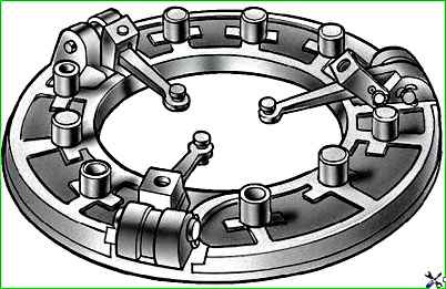
After removing the pressure and driven bolts (Fig. 4), the discs can be freely pulled down.
Installing the disks on the car is done in reverse order.
Before installation, do the following:
- 1. Wipe all friction surfaces of the discs and flywheel with a clean cloth dampened with gasoline.
- 2. Blow air through the clutch disc parts and inspect them to identify possible defects.
- 3. Add grease to the transmission input shaft bearing mounted on the crankshaft.
- 4. Install the driven and pressure plates into the clutch housing and, through the rear hole of the clutch housing, center the driven disc relative to the flywheel using a mandrel 55–1187 inserted into the crankshaft bearing.
Instead of a mandrel, you can use the gearbox input shaft.
The short part of the driven disc hub should face the flywheel.
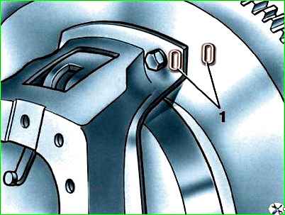
- 5. Align the “O” marks (see Fig. 5) on the flywheel and pressure plate housing and tighten the six housing mounting bolts.
Tighten the bolts evenly and sequentially around the circumference.
Disassembling the pressure plate
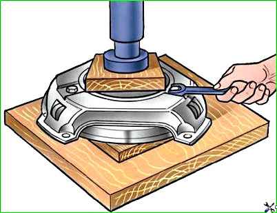
The pressure plate parts are under the force of six springs.
Therefore, before unscrewing the bolts securing the supports of the pull-out levers, they should be unloaded by squeezing the disk with a press, as shown in Fig. 6.
Disassemble the pressure plate in the following order:
- 1. Make marks on the casing and disk for their relative positions so as not to disturb the balancing during assembly.
Also make marks on the levers and pressure plate.
- 2. Unscrew the three bolts securing the casing to the release arm supports.
- 3. Smoothly release the casing from under the press, remove the casing, springs and spring washers.
- 4. Unpin and remove the pins of the pull-out levers, remove the lever supports (forks) and remove the rollers from the levers.
Assembling the pressure plate
Assemble the pressure plate as follows:
1. Place 19 rollers into the holes of the pull arms. For ease of assembly, so that the rollers do not fall out, lubricate them with Litol-24 grease.
Do not use grease for this purpose.
In the absence of lubrication, the rollers can be assembled using a cylindrical mandrel with a diameter of 8 mm and a length of 9 mm, around which dry rollers are placed in the holes.
After installing the rollers, lubricate them with 2-3 drops of gear oil.
- 2. Insert the assembled pull-out levers into the grooves of the pressure disk in accordance with the markings made during disassembly, insert the pins of the levers (the mandrels will come out) and pin them (Fig. 7).
- 3. Install the support forks on the levers so that the finger is positioned towards the pressure plate and the roller towards the casing.
Splint the pins of the forks.
- 4. Assemble the disc with the casing and springs under a press to compress the springs and screw the bolts into the support forks.
Place the driven disk (or a template replacing it, 9.5 mm thick) under the press.
Place the pressure plate assembled with levers on the driven disk; Install heat-insulating washers and springs onto the protrusions for the pressure springs.
- 5. Install the clutch cover onto the pressure plate so that the marks made during disassembly match.
Make sure that every I got the spring onto the corresponding protrusion in the casing.
Use a press to press the casing against the table until it stops, as shown in Fig. 5. There should be no distortions in the casing.
Tighten the three bolts securing the support forks.
- 6. Adjust the position of the heads of the adjusting bolts of the retraction arms.
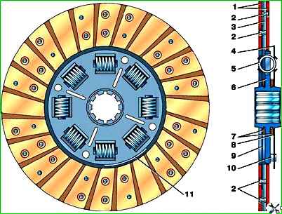
Replacing the friction linings of the driven disk
Replace the friction linings of the driven disk if cracks have formed in the linings or holes for rivets have developed, and also if the linings are worn out so that less than 0.5 mm remains from the friction surface to the rivet heads.
As a rule, if you replace one pad, you should also replace the other.
To replace the linings, carefully drill out the rivets securing them (rivet shaft diameter is 4 mm) and remove the remaining rivets so as not to damage the spring plates of the disk.
After replacing the linings, check the runout of the rubbing surfaces of the new linings relative to the spline hole.
The runout measured at a radius of 125 mm should not be more than 0.7 mm.
If it exceeds the specified value, then the driven disk must be corrected.

")
")
")
")
")