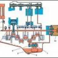
The lubrication system diagram is shown in Fig. 1.
Oil pressure in the lubrication system of a warm engine at low crankshaft speed 550–650 min -1
- – for engines models 414, 4178; 700–750 min -1
- – for engines model 4218) at idle with the oil cooler tap open, there must be at least 39 kPa (0.4 kgf/cm 2);
- - on an unheated engine, the pressure can reach 441–490 kPa (4.5–5.0 kgf/cm 2);
- - at a vehicle speed of 45 km/h the pressure should be 196–392 kPa (2.0–4.0 kgf/cm 2), and in hot summer weather at least 147 kPa (1 .5 kgf/cm 2).
Pressure in the lubrication system less than the specified values indicates a malfunction in the engine.
The engine operation must be stopped until the malfunction is eliminated
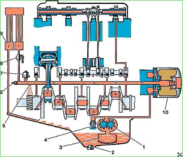
To cool the oil in the lubrication system, an oil cooler is installed, which is turned on by opening the tap when the air temperature is above 20°C.
At lower temperatures the radiator should be turned off.
However, regardless of the air temperature, when driving in difficult conditions (with a heavy load and high engine speed), it is also necessary to open the oil cooler valve.
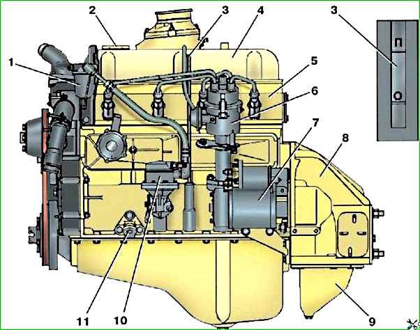
Maintain the oil level in the engine crankcase near the “P” mark on oil measuring rod 3 (see Fig. 2).
Measure the oil level 2-3 minutes after stopping the warm engine.
Do not pour oil above the “P” mark, as this will lead to increased oil splashing and, as a result, coking of the rings, carbon formation in the combustion chamber of the cylinder head and on the piston heads, oil leakage through the seals and gaskets.
Lowering the oil level below the “O” mark can damage the engine bearings.
With an oil pressure difference of 58–73 kPa (0.6–0.7 kgf/cm 2) before and after the filter.
To replace the filter, unscrew it by rotating it counterclockwise.
When installing the oil filter, make sure that the rubber sealing gasket is in a special groove in the filter housing.
When operating the vehicle, monitor the operation of the oil pressure sensors. The emergency oil pressure sensor is triggered when the pressure in the system drops to 39–78 kPa (0.4–0.8 kgf/cm 2).
When the ignition is turned on, the emergency oil pressure lamp lights up and goes out after the engine starts.
Lighting of the lamp in operating modes indicates a malfunction of the sensor or engine lubrication system.
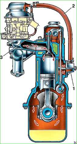
If oil consumption is increased (and there is no leakage), check the serviceability of the crankcase ventilation system (Fig. 3) and the condition of the sealing caps, valves and cylinder-piston group.

")
")
")
")
")