The diesel power system serves to supply air and fuel to the engine cylinders
Fuel is supplied under high pressure at certain moments and in a certain amount depending on the engine load
The air supply system thoroughly cleans it of dust and distributes it among the cylinders. Mixing of fuel with air occurs inside the cylinder.
Information about diesel fuel
Depending on the conditions of use, according to GOST 305-82, the following grades of diesel fuel are established: L (summer), 3 (winter) and A (arctic). Their choice depends on the time of year and climatic conditions in the area of application.
Fuel L is used at air temperatures of 0 °C and above;
- 3 - at ambient air temperature - 20 °C and above (if the pour point of the fuel is not higher than - 35 °C), - 30 °C and above (if the pour point of the fuel is not higher than - 45 °C);
- A - at ambient temperature - 50 °C and above.
The pour point of winter fuel corresponds to the last digit in its designation.
Summer fuel is more viscous; at subzero temperatures it releases paraffin in the form of flakes, and at 10 °C it loses its fluidity.
The last digit in the designation of summer diesel fuel characterizes the flash point.
The sulfur content in the fuel characterizes its corrosive properties.
Depending on the sulfur content, diesel fuels are divided into two subgroups: with a sulfur mass fraction of no more than 0.2% and with a sulfur mass fraction of no more than 0.5% (for grade A fuel no more than 0.4%).
Thus, fuels of the second subgroup contain approximately twice as much sulfur.
For KamAZ engines, fuel of both subgroups can be used, since they use motor oil with an additive that reduces the harmful effects of sulfur.
Let's look at examples of diesel fuel designations:
- L-0.2-40 GOST 305-82 - summer fuel, sulfur content up to 0.2%, flash point 40 °C;
- Z-0.5 minus 35 GOST 305-82 - winter fuel, sulfur up to 0.5%, pour point -35 °C;
- A-0.4 GOST 305-82 - arctic fuel, sulfur up to 0.4%.
One of the important indicators characterizing diesel fuel is flammability.
The fuel injected into the cylinder does not begin to burn immediately, but after some time, called the ignition delay period.
The longer the delay, the more fuel accumulates at the time of ignition and the faster the pressure in the cylinder subsequently increases.
This leads to shock loads on the parts and is accompanied by metallic knocks (“hard” work).
The degree of “hardness” of diesel operation depends on the ignition properties of the fuel and is characterized by the cetane number.
The larger it is, the shorter the auto-ignition delay period, the easier it is to start the engine and the “softer” its operation.
Diesel fuels L, 3 and A have cetane numbers of at least 45.
Mixture formation and fuel combustion
The formation of the working mixture begins from the moment a dose of fuel is injected into the combustion chamber.
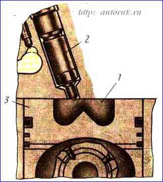
The combustion chamber (Fig. 1.) is limited by the piston bottom and the inner surface of the cylinder head.
Such combustion chambers are called undivided.
The main volume of the chamber is concentrated in the recess of the piston bottom, which has a cone-shaped protrusion (displacer) in the central part.
As the piston approaches top dead center (TDC) during the compression stroke, air from the cylinder is forced into the combustion chamber, creating vortex flows during movement that contribute to better mixture formation.
By the time fuel injection begins, this chamber contains air compressed to 4-4.5 MPa and heated (from compression and the hot wall of the chamber) to a temperature of 620-700 °C.
So that the fuel can penetrate such a compressed environment, it is injected under high pressure of 24 MPa.
This allows you to obtain a fine atomization of the fuel and mix it well with air.
A feature of a diesel engine is that the same amount of air actually enters the cylinder regardless of the load.
At low load, excess air forms in the cylinder and the fuel burns completely.
As the load increases, the fuel supply increases and its combustion worsens.
The nature of engine operation is affected by the ignition delay period. It depends both on the properties of the fuel itself and on the temperature in the combustion chamber and the injection advance angle.
Too large an injection advance angle leads to an increase in the ignition delay period and “hard” engine operation, since in this case, the start of injection occurs at relatively low temperatures in the cylinder.
A small advance angle promotes fuel combustion during the expansion stroke, which worsens the temperature conditions of the engine, causing it to overheat.
For an idle KamAZ engine, the injection advance angle is 18° to . m.t.
On a running engine, as the crankshaft speed increases, the pressure and temperature at the end of the compression stroke increase, so the conditions of mixture formation and combustion change.
The duration of the combustion process increases and in this case it is advisable to increase the injection advance angle.
The angle is increased automatically by the injection advance clutch, which acts on the high-pressure fuel pump when a certain crankshaft speed is reached.
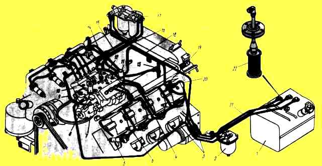
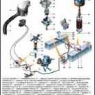
The diagram of the KamAZ diesel power system is shown in the figure
The fuel is contained in tank 1, which is connected by a fuel suction line through a coarse filter 2 to a low-pressure fuel pump 7.
When the engine is running, a vacuum is created in the suction line, as a result of which the fuel passes through the coarse filter 2, is cleared of large suspended particles and enters the pump 7, from which, under low pressure, the fuel line 9 is supplied to the fine filter 17.
Next, the purified fuel is supplied to the high-pressure fuel pump 10, from the channels of which part of the fuel is pumped to the injectors 5 and through them injected into the cylinders.
The other part of the fuel is diverted into the tank through the bypass valve.
Due to the operation of the bypass valve, a pressure of 50-110 kPa is constantly maintained in the pump channels.
To remove air trapped in the fuel system, fine filter 17 is located above all other devices in this system and is equipped with a nozzle valve through which air, along with part of the fuel, is discharged through fuel line 18 into the tank.
Through the same fuel line, fuel from high-pressure pump 10 is drained into the tank, which is supplied to the fitting on the filter through the bypass valve and fuel line 16.
Fuel lines 4 and 14 serve to drain fuel that has leaked between the injector parts into the tank.
The high-pressure pump is driven from the engine crankshaft through an injection advance clutch, which automatically changes the timing of fuel injection when the rotation speed changes.
The amount of fuel supplied to the cylinders by the high-pressure fuel pump is set by the regulator, which automatically maintains the crankshaft speed set by the driver.
Manual fuel pump 8 is used to fill the low pressure line with fuel when the engine is not running.
Fuel line 12 is connected to the low-pressure line; through it, fuel is supplied to the flare plugs 13 through the open solenoid valve 11 when starting a cold engine using an electric flare device.
Fuel equipment
Fuel tanks used on KamAZ vehicles have a capacity of 250 and 170 liters.
Tanks are installed on brackets and secured with clamps. The support brackets are bolted to the frame side members.
The fuel tank consists of a housing, a filler neck and a retractable pipe with a mesh filter.
The filler neck is closed with a lid with a steam-air valve and sealed with a rubber gasket.
The inner surface of the tank is leaded to protect against corrosion
To reduce fuel agitation and increase the rigidity of the tank, vertical partitions with holes are welded inside it.
In the upper part of the tank there is a rheostat sensor for the fuel level indicator and a tube through which excess fuel from the engine injectors is drained.
A intake tube is installed next to it, ending at the bottom of the mesh with a fuel pre-filter.
On KamAZ-4310 vehicles with two fuel tanks, a distribution valve is installed on the intake pipe of the left tank.
The same valve is installed on the tube into which excess fuel not used in the high-pressure pump is drained.

")
")
")
")
")