To diagnose the pneumatic drive of brake systems, you must have at least one control pressure gauge and use the control outlet valves available on the vehicle
Working with one pressure gauge is very labor-intensive, and using only standard control valves makes troubleshooting a number of devices much more difficult.
Therefore, when performing an in-depth check of the performance of the pneumatic drive, you should use a set of control pressure gauges, as well as a set of fittings, adapters and connection heads that allow you to measure the pressure in any line.
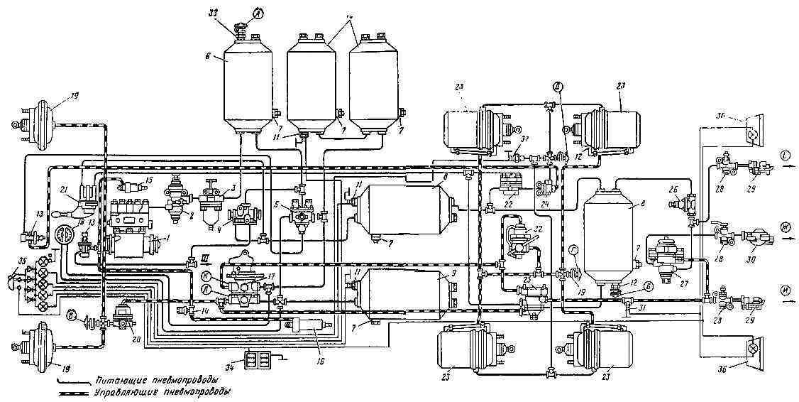
Diagram of the pneumatic drive of the brake mechanisms: A - control valve of the IV circuit; B, D - valves of the control output of the third circuit; B - control valve of the first circuit; G - control valve of the 2nd circuit; K, L - additional control valves; I - brake (control) line of a two-wire drive; F - connecting line of a single-wire drive; E - supply line of a two-wire drive; 1 – compressor; 2 - pressure regulator; 3 - frost protection; 4 - double safety valve; 5 - triple safety valve; 6 - condensation receiver; 7 - condensate drain valve; 8 - receiver of the third circuit; 9 - air receiver of the first circuit; 10 - receiver of the second circuit; 11 - pressure drop sensor in the receiver; 12 - control valve; 13 - pneumatic valve; 14 - trailer brake solenoid valve activation sensor; 15 - pneumatic cylinder for driving the engine stop lever; 1c - pneumatic cylinder for auxiliary brake flap drive; 17 - two-section brake valve; 18 - two-pointer pressure gauge; 19 - brake chamber type 24; 20 - pressure limitation valve, - 21 - parking and emergency brake control valve; 22 - accelerator valve; 23 - brake chamber type 20/20 with a spring energy accumulator; 24 - two-line bypass valve; 25 - trailer brake control valve with a two-wire drive; 26 - single protective valve; 27 - trailer brake control valve with a single-wire drive; 28 - disconnect valve; 29 - Palm type connection head; 30 - connection head type A; 31 - brake light sensor; 32 - automatic brake force regulator; 33 - air bleed valve; 34 - batteries; 35 - block of warning lamps and buzzer; 36 - rear light; 37 - parking brake sensor
First, the serviceability of the lamps and buzzer is checked. When you press the button in the block, the indicator lamps should light up.
The lamps light up if the pressure in the corresponding cylinders is below 4.8-5.2 kgf/cm 2. The buzzer works if at least one lamp is on.
Next, after starting the engine, fill the pneumatic drive with compressed air.
At an engine speed of 2200 rpm, a working compressor pumps up the brake system (the lights go out) in 8 minutes.
If the filling time is longer, the pneumatic drive may be leaking, the filter in the regulator is dirty or frozen, or the valves in the compressor are faulty.
If the cylinder-piston group is worn out, then, having low performance, the compressor, together with air, will supply oil to the pneumatic drive, which accumulates along with condensate in the cylinders and is discharged from the pressure regulator.
When the pressure in the system reaches 7.0-7.5 kgf/cm 2 the pressure regulator is activated, and air from the compressor continuously exits through the atmospheric outlet. Press and release the brake pedal several times.
The pressure in the pneumatic drive will decrease to 6.2-6.5 kgf/cm 2.
The unloading valve in the pressure regulator will close, and the compressor will again increase the pressure in the pneumatic drive to 7.0-7.5 gf/cm 2.
The opening and closing pressure of the valve in the pressure regulator is monitored by a two-pointer pressure gauge in the cabin or by a pressure gauge connected to the control valve on the condensation bottle.
You need to regulate the air pressure in the pneumatic drive using the screw on top of the pressure regulator.
Deviations in the operation of the pressure regulator: a sudden release of air during the filling of the system, opening of the valve at low or high pressure and the impossibility of adjusting it - indicate a malfunction of the device and the need for its repair.
Check the pneumatic brake actuator for leaks
When the compressor is not working and consumers are turned off (the brake pedal is released, the parking brake is on), the pressure drop during 30 minutes of testing should be less than 0.5 kgf/cm 2.
When the consumers are turned on (the brake pedal is pressed, the parking brake is off), the pressure drop during 15 minutes of testing should also be less than 0.5 kgf/cm 2.
To check the operation of the safety valves, connect a pressure gauge to the control outlet valve on the parking brake cylinder.
Bleed the air from the front axle cylinder using the condensate drain valve.
The pressure drop should only be shown by the upper arrow of the standard pressure gauge.
The pressure in the rear bogie and parking brake cylinders should not change.
If the pressure decreases in the rear bogie cylinders, then the triple safety valve is faulty, and the drop in pressure in the parking brake cylinders indicates a malfunction of the double or single safety valve (depending on the layout of the pneumatic actuator) feeding this circuit.
In order to check the serviceability of the pneumatic drive of the service brake, you need to attach pressure gauges to the control valves on the pressure limiter and on the rear of the frame above the rear axle.
The readings of these pressure gauges correspond to the pressure in the front brake chambers and the brake chambers of the rear bogie.
When you press the brake pedal all the way, the pressure on the two-pointer pressure gauge should decrease by no more than 0.5 kgf/cm 2 (air from the cylinders entered the brake chambers, and the pressure dropped), the pressure in front brake chambers should increase to 7.0 kgf/cm 2 and become equal to the readings of the upper scale of the pressure gauge in the cabin.
The pressure in the rear brake chambers also increases to 2.5-3.0 kgf/cm 2 for an empty car.
If you raise the vertical rod of the brake force regulator drive up by the amount of static deflection of the suspension, then the pressure in the rear brake chambers should increase to 7.0 kgf/cm 2 (lower scale reading of the pressure gauge). p>
The static deflection of the suspension when loading depends on the stiffness of the springs, so for basic models it is respectively: KamAZ-5320 - 40 mm, KamAZ-5410 - 42 mm, KamAZ-5511 - 34 mm.
The brake force regulator drive is regulated by changing the length of the vertical rod and changing the length of the regulator lever.
The rod length is set so that when the car is empty and the brake pedal is fully pressed, the pressure in the rear brake chambers is not lower than 2.5 kgf/cm 2.
The length of the regulator lever is set constant for this model:
KAMAZ-5320 - 105 mm, KamAZ-5410 - 105 mm, KamAZ-5511 - 95 mm. After releasing the brake pedal, the air from the brake chambers should come out without delay and completely.
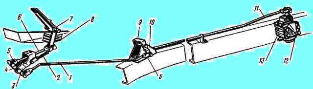
If the nominal pressure (7.0 kgf/cm 2) is not provided in the front and rear brake chambers when the pedal is fully pressed, then it is necessary, first of all, to check the correct adjustment of the mechanical drive of the brake valve ( Fig. 1).
The drive has two adjusting forks: on the pedal link and on the intermediate link. Access to the first adjusting fork is provided when the front end trim is raised.
By shortening the pedal rod, we raise the pedal in the cabin, the full pedal stroke increases, it should be equal to 100-140 mm.
When the pedal is fully pressed, the lever travel of the two-section brake valve is 31 mm.
In operation there are cars that have a long release time, often due to the lack of free play in the brake pedal, which is regulated by the fork on the intermediate link and should be 20-40 mm.
If the maximum pressure in one of the service brake circuits is not ensured, and the pressure in the other is normal, then it is necessary to connect a pressure gauge to the output of the corresponding section of the brake valve: to the top - if the rear trolley circuit is not working properly, to the bottom - if the front trolley circuit is not working properly bridge.
Pressure gauges must be connected to the side (along the vehicle) terminals instead of stop sensors - signals on dump trucks or pipelines going to a two-wire valve on tractor-trailers.
When you press the pedal, you need to compare the pressure at the outlet of the brake valve and in the brake chambers.
When you press the pedal fully, the pressure values at the outlet of the brake valve and pressure limiter should be equal.
The pressure in the rear brake chambers depends on the position of the brake force regulator lever: in the lower position “empty” - 2.5 kgf/cm 2, in the upper position “loaded” - 7.0 kgf/cm 2.
By comparing pressure gauge readings and knowing the characteristics of the devices, you can easily find out which one is faulty.
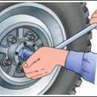
When braking with the service brake, you need to check the stroke of the brake chamber rods.
For KamAZ-5320, 5410, 55102 vehicles it is 20-30 mm, KamAZ-5511, KamAZ-53212, 54112 - 25-35 mm. The difference in the stroke of the brake chamber rods on one axle is allowed - 2-3 mm.
To check the functionality of the parking brake circuitit is necessary to connect a pressure gauge to the control valve on the rear of the frame and check the pressure in the energy accumulators.
When the parking brake valve handle is in a vertical position, the car is braked by the force of the springs in the energy accumulators, the pressure in them is atmospheric.
If you move the valve handle to a horizontal position, air from the parking brake cylinders will flow through the accelerator valve into the energy accumulators, the springs will compress, and the car will release the brakes.
The pressure on the control pressure gauge should increase to 7.0 kgf/cm 2.
Check the operation of the spare brake by smoothly moving the parking brake valve handle to a vertical position.
When the angle of rotation of the handle is up to 30°, the pressure in the energy accumulators should decrease to 5.0-4.5 kgf/cm 2, and the rods of the rear brake chambers should begin to move downward.
Further smooth rotation of the parking brake valve handle causes a synchronous decrease in pressure in the energy accumulators and extension of the rods.
When the angle of rotation of the parking brake valve handle is 60-70˚, the pressure should drop to zero. If this does not happen, then it is necessary to replace the faulty parking brake valve.
When checking the functionality of the emergency brake release circuit you need to turn on the parking brake (the pressure in the energy accumulators is atmospheric).
By pressing the emergency brake release valve button, we transfer air from the service brake cylinders to the energy accumulators.
When the pressure in the energy accumulators reaches 4.8-5.2 kgf/cm 2 the flashing light in the control lamp block goes out.
Complete release of the brake requires 6-8 seconds. On the pressure gauge in the cabin, the pressure drop when releasing the brakes should be no more than 0.8 kgf/cm 2.
After releasing the valve button, the air from the energy accumulators is completely released through the valve into the cabin, and the parking brake is activated.
When the parking brake is applied, a flashing light in the warning lamp unit lights up.
Before checking the auxiliary brakestart the engine and then press the brake valve button.
The engine must stop, since turning the lever on the high-pressure fuel pump will turn off the fuel supply and close the dampers in the exhaust pipes.
The engine stop lever and the damper are driven by pneumatic cylinders.
When braking with the auxiliary brake, air is also supplied to the normally open sensor that controls the solenoid valve on the trailer.
The valve is activated and allows compressed air from the trailer cylinder into the brake chambers.
The pressure in the trailer brake chambers is set constant - 0.6-0.8 kgf/cm 2, it is regulated by a screw at the bottom of the solenoid valve.
To check the operation of the devices that control the trailer, you need to attach a pressure gauge to the Palm head of the supply line and open the isolation valve. In this case, the pressure gauge should show a pressure of 6.2-7.5 kgf/cm 2.
Then we attach the pressure gauge to the head from the “Palm” control line and open the isolation valve.
When the tractor is released, the pressure in this line is atmospheric.
If you brake the car with the service or parking brake, the pressure should increase synchronously in accordance with the angle of rotation of the parking brake valve handle or the force of pressing the pedal from zero to 6.2-7.5 kgf/cm 2 .
You can check the correct adjustment of the two-wire valve by fixing the brake force regulator lever in the “loaded” position.
In this case, the pressure in the rear brake chambers, with a working regulator, will be equal to the pressure in the upper, control section of the two-wire valve.
By comparing the readings of the pressure gauge that measures the pressure in the trailer control line and the pressure gauge that measures the pressure in the rear brake chambers with the regulator lever raised, it is possible to determine the excess pressure.
It should be 0.6 kgf/cm 2 and adjusted at a pressure value of 3-4 kgf/cm 2.
When screwing in the screw located inside the two-wire valve, the excess pressure in the control line increases.
Check the operation of the brake light sensor. The sensor contacts must close and turn on the brake lights when pressure in the trailer control line 0.1-0.5 kgf/cm 2.
To check the operation of the brakes using a single-line drive, it is necessary to attach a pressure gauge to head “A” of the single-line line and open the isolation valve.
When the tractor is released, the pressure in this line should be in the range of 4.8-5.3 kgf/cm 2. This pressure is adjusted by a screw at the bottom of the single line valve.
When braking with a service, parking or spare brake, the pressure in the single-line line should decrease with full braking from 4.8-5.3 kgf/cm 2 to zero.
To check the brakes on a trailer, you must connect pressure gauges to the control valve to check the pressure in the rear brake chambers and to the control valve on the trailer tank.
When trailer brakes operate via a two-line drive, the pressure in the cylinder should be 6.2-7.5 kgf/cm 2.
When braking a trailer with a service or parking brake, the pressure in the brake chambers increases from 0 to 3.0 kgf/cm 2, if the trailer is empty.
When the regulator lever is raised to the “loaded” position, the pressure should increase to 6.2-7.5 kgf/cm 2.
When the solenoid valve is turned on, the pressure in the brake chambers is set to 0.6-0.8 kgf/cm 2.
After releasing the brakes, the compressed air must be released into the atmosphere completely, without delay.
To switch the trailer to work with a single-wire drive you need to close the disconnect valves in the supply and control lines of the tractor.
As soon as the isolation valve in the supply line closes, the compressed air from the trailer cylinder will exit through the equalizing valve in the air distributor and then through the valve into the atmosphere.
The pressure in the trailer cylinder should drop to 4.8-5.3 kgf/cm 2, and after that the trailer brakes should turn on.
The pressure in the single-line line must be equal in value to the pressure in the cylinder. If these values are not equal, then the closing pressure of the equalizing valve should be adjusted with the screw on the air distributor.
Connect the trailer using a single-wire drive.
When braking an empty trailer, the pressure in the brake chambers must be at least 3.0 kgf/cm 2, and with the regulator lever raised it will increase to 4.8-5.3 kgf/cm 2.
If, based on the results of the check, the pressure values at the control points correspond to the specified values, the pneumatic drive of the brake systems of the tractor and trailer is serviceable and operational.

")
")
")
")
")