Brake mechanisms of rear wheels ZIL-5301
The brake mechanisms of the rear wheels are shoe, drum type. The design of the brake mechanisms is shown in Fig. 1
To disassemble the brake mechanism of the rear wheels, you need to clean the brake drum from dirt and make sure it rotates freely.
The parking brake system must be in the released state.
Unscrew the six bolts securing the brake drum to the rear wheel hub and remove it, turning it so that the protrusions on the drum coincide with the grooves on the hub.
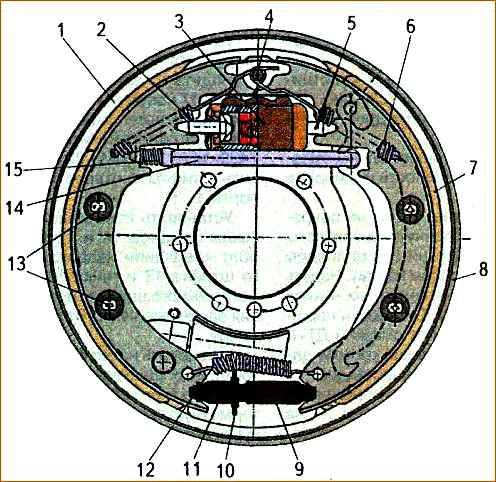
To dismantle the pads, use a wire loop or hook to remove springs 2 and 6 from support pin 4; disassemble the rods 13 that secure the pads to the brake shield 8, recessing the upper cup, and turning it until the groove in the cup coincides with the position of the rod, remove the tension spring 12.
Disconnect the parking brake release lever 14 and spring 15 from the pads.
After disassembling the brake mechanism, all parts must be washed with MS-6 or MS-8 washing solution TU 6-12-978-76, blown with compressed air and carried out defect detection
Inspect the inner working surface of the drum and check the thickness of the linings on the primary 1 and secondary 7 pads.
Cracks and chips on brake parts are not allowed. Damage to the thread is allowed no more than two threads. Brake lining wear is allowed to a level of 1-5 mm up to the rivet heads.
If brake parts are worn beyond the permissible dimensions, the worn parts must be replaced.
It is recommended to correct bent brake shield by straightening. If the shields are more bent, they must be replaced.
When assembling the brake mechanism of the rear wheels, all operations must be done in the reverse order of disassembly. In this case, you need to keep the following in mind.
The position of the secondary and primary pads and pad springs must not be interchanged.
The primary brake pad differs from the secondary spring, which has a larger number of turns and a smaller wire diameter.
When installing tension spring 12 (see Fig. 1) and adjusting screw 10, nut 9 must be screwed in completely to compensate for the thickness of the new linings.
If only one brake pad on the rear wheels on a vehicle is worn out, all four rear brake pads should be replaced.
During assembly, the bearing surfaces of the bushings and axles must be lubricated with a thin layer of lubricant.
Gluing new linings to the brake pads. If necessary, you can replace the brake linings on the pads by gluing new ones.
To ensure reliable adhesion of the friction linings to the brake pads, the following conditions must be met.
Gluing is carried out using glue brand VS-10T GOST 22345-77 or TIIR-4 TU 38.114513-96 from OJSC SNIIATI (Yaroslavl).
Before gluing the brake pads, the brake pads must be mechanically cleaned from traces of old ones, provided that the geometric shape is maintained according to the drawing.
After mechanical processing of the pads, contamination of the prepared surface with dust, oil and other substances that weaken the adhesive joint is not allowed.
The glossy layer on the inner surface of the lining must be removed while maintaining the geometric dimensions of the product. Irregularities, cracks, traces of oil and surface contamination are not allowed.
On clean, grease-free surfaces of the pads and linings, apply a uniform layer of glue with a brush at the rate of 1.5-2 g per 100 cm 2 area.
After applying the glue, the parts must be dried in air for at least 15 minutes and no more than 90 minutes at a temperature not lower than 15°C. It is not allowed to touch the surface coated with glue with your hands.
Gluing of parts must be done in a special device that ensures the correct relative position of the lining and block and with pressing of the lining to the block with a force of 49-78 N/cm 2.
Gluing of parts must take place in a drying oven at a temperature of 180°C for 120 minutes, excluding the time it takes for the oven to warm up to the specified temperature.
After gluing the overlays, the product must be checked for cracks, chips, distortion, absence of a gap between the overlay and the block, and compliance with the drawing.
The strength of the adhesive joint must comply with GOST RISO 6312-93. The breaking force must be at least 100 N/cm 2.
Adjusting the rear wheel brakes
As the friction linings wear out, it is necessary to adjust the gap between the pad lining and the drum at intervals of 4000 km.
To adjust, do the following:
- 1. turn off the parking brake;
- 2. raise the rear wheels;
- 3. remove the spring plugs from the rear brake shields;
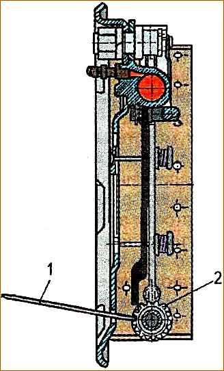
- 4. through the hole in the brake shield, use a special blade 1 (or a wide screwdriver) to rotate the sprocket of the adjusting screw 2 (on the left brake from bottom to top; on the right - in the opposite direction), spreading the pads until the wheel brakes (does not turn by hand).
Rotate the sprocket in the opposite direction to ensure free rotation of the wheel;
- 5. insert spring plugs.

")
")
")
")
")