Adjusting the fuel supply ZIL-5301
To adjust the amount and uniformity of fuel supply to the pump sections, do the following.
Before adjusting the pump, check for uniformity and quantity of fuel supply to each section:
- tightness of discharge valves by turning off the fuel supply with the control lever.
Fuel leaks are not allowed. In case of leakage, replace the discharge valve assembly;
- - fuel pressure in the suction cavity of the fuel pump, which should be 0.07-0.13 MPa;
- - no air leaks at the fuel line connections.
Adjust the amount of fuel supplied by each section of the pump and. uniformity of feed across sections at a rotation speed of 1200 min -1 in accordance with the adjustment table.
Control unevenness of fuel supply according to GOST 10578.
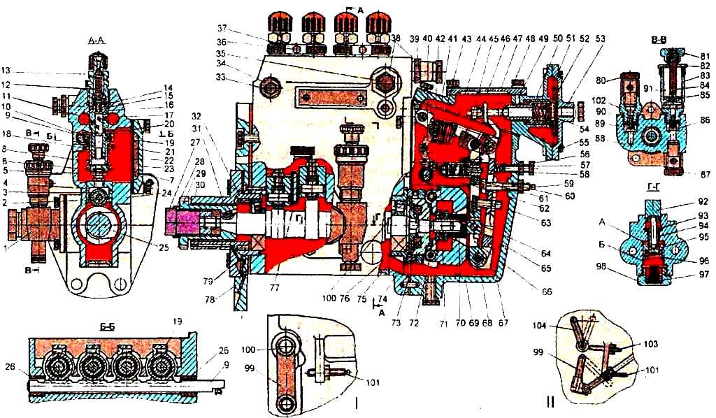
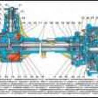
High pressure fuel pump: I – version of a single lever injection pump; II – version of a double-lever injection pump; 1 – fuel priming pump; 2 – pusher roller bushing; 3 – pusher roller; 4 – plunger pusher; 5 – pusher adjusting bolt with lock nut; 6 – lower plate; 7 – plunger shank; 8 – plunger spring; 9 – rack; 10 – ring gear; 11 – fuel outlet channel; 12 – spring; 13 – fitting; 14 – discharge valve; 15 – gasket; 16 – discharge valve seat; 17 – fuel supply channel; 18 – plunger bushing; 19 – tightening screw; 20 – pin; 21 – upper plate; 22 – rotary plunger sleeve; 23 – cover; 24 – fuel injection pump housing; 25 – cam shaft; 26 – rack nut; 27 – nut; 28 – washer; 29 – splined bushing; 30 - installation flange; 31 – key; 32 – spring; 33 – air release plug; 34 – futorka; 35 – bypass valve; 36 – bolt; 37 – clamp; 38, 102 – footers; 39 – boost corrector housing; 40 – spring lever; 41 – starting enrichment spring; 42 – finger; 43 – earring; 44 – regulator spring; 45 – rack rod; 46 – emphasis; 47 – boost corrector cover; 48 – main regulator lever; 49 – pin; 50 – bushing; 51 – diaphragm; 52 – plate; 53 – boost corrector cover; 54 – rod; 55 – screw; 56 – bolt; 57 – idle spring; 58 – corrector rod; 59 – adjusting shims; 60 – hard stop; 61 – corrector housing; 62 – bracket; 63 – bolt; 64 – heel; 65 – axis of the intermediate lever; 66 – intermediate lever; 67 – speed regulator housing; 68 – lever axis; 69 – cargo; 70 – regulator coupling; 71 – adjusting screw; 72 – load axis; 73 – hub; 74 – elastic drive with rubber elements; 75 – thrust washer; 76 – bearing cup; 77 – plate clamp; 78 – pump mounting plate; 79 – bearing; 80 – square bolt; 81 – handle-nut; 82 – cover; 83 – vertical cylinder; 84 – rod; 85 – piston of the fuel pump; 86 – inlet nylon valve; 87 – rotary square; 88 – body; 89, 96 – springs; 90 – discharge valve; 91 – fuel pump; 92 – pusher; 93 – guide sleeve; 94 – rod; 95 – piston of the fuel pump; 97 – emphasis; 98 – plug; 99 – fuel supply control lever; 100 – control lever shaft; 101 – maximum rotation speed adjustment screw; 103 – engine stop lever adjustment screw; 104 – engine stop lever
Adjust the cyclic fuel supply at the nominal rotation speed using hard stop 60 (see Fig. 1).
When screwing a bolt (inside the body), the feed increases, when turning it out, it decreases.
Adjust the fuel supply in the maximum torque mode (700-800 min -1) by changing the position of screw 71 of the corrector.
To achieve a rotation speed corresponding to turning off the corrector (complete sinking of the corrector rod), it is necessary:
- if the frequency is too high (more than 800 min) - unscrew the adjusting screw from the corrector body;
- at a low rotation speed (less than 700 min -1) - screw the screw into the corrector housing.
The amount of cyclic feed is determined by the stroke of the corrector rod, which should be equal to 0.5-0.7 mm.
To determine the parameters for adjusting the cyclic feed, it is necessary to determine the cyclic feeds in the rotation speed range, expanded in comparison with the adjustment table by 50 minutes -1 in each direction after 50 minutes -1
To calculate the maximum correction factor, the largest (of the measured) cyclic transmission must be selected.
The uniformity of fuel supply and the performance of each pump section must be adjusted by moving the rotation of the rotary sleeve relative to the ring gear when the tension screw is loosened.
When the bushing is turned to the left, the fuel supply to the section increases, when turned to the right it decreases.
After adjusting the pump section, tighten the ring gear clamp screw securely.
If it is necessary to change the fuel supply to all 4 sections at the same time, it is possible to change the position of the hard stop, after which it is necessary to check the start of operation of the regulator and the uniformity of fuel supply across the sections.
Check the fuel supply at maximum idle speed, which should be 22.5 mm 3 cycle at a speed of 1250 min -1.
Screw bolt 56 (see Fig. 1) with the idle spring at maximum idle speed until the free end of the spring touches the main lever of the regulator and secure with a nut.
Check the cyclic fuel supply at a rotation speed of 90-100 min -1, corresponding to the start mode.
The average cyclic fuel supply at this rotation speed must be at least 140 mm/cycle when the control lever is installed all the way to the maximum rotation speed screw.
Check the forced complete shutdown of the fuel supply at a rotation speed of 100 min -1, moving the regulator control lever to the extreme position in the direction of decreasing the supply.
Adjusting the boost corrector
The start of the rod movement should occur at an air pressure in the above-diaphragm space equal to 0.005-0.010 MPa.
In the absence of pressure in the above-diaphragm space, the average cyclic flow is set by moving the stop 46 (see Fig. 1) and should be 60-70 mm 3/cycle at a pump camshaft speed of 550 min -1.
Adjustment of the start of movement of the diaphragm 51 (rod 54) must be done by changing the pre-compression of the spring by screwing in or unscrewing the sleeve 50.
The movement of the sleeve 50 towards the diaphragm increases the air pressure corresponding to the start of the diaphragm; the movement of the sleeve away from the diaphragm reduces the air pressure corresponding to the start of the diaphragm operation.
After adjusting the start of movement of the diaphragm (rod), install pin 49 into the hole in the corrector body.
When installing the pin, make sure that its upper end does not protrude above the upper plane of the CPN body, for which, if necessary, turn the corrector bushing 50 in one direction or another by no more than 30°.
The pressure at which the diaphragm (rod) begins to move must remain within the established limits.
The pressure corresponding to the end of the CPN response is determined by a series of sequential performance measurements in the pump sections at the corresponding rotation speed of the fuel pump camshaft.
The end of the CPN operation should be at a frequency of 550 min -1 and a pressure of 0.012-0.015 MPa.

")
")
")
")
")