Repair of connecting rods comes down to replacing the upper head bushing and then processing it to fit a piston pin of a nominal size or to processing the bushing available in the connecting rod for a repair-size pin
Spare parts are supplied with bushings of the same size, made of 1 mm thick OTS4-4-2.5 bronze tape.
When pressing a new bushing into the connecting rod, ensure that the hole in the bushing matches the hole in the upper head of the connecting rod.
The holes are used to supply lubricant to the piston pin.
After pressing the bushing, compact its inner surface with a smooth brooch to a diameter of 24.3 +0.045 mm, and then expand or bore to the nominal or repair size with a tolerance of +0.007 -0.003 mm.
For example, expand or bore the bushing for a nominal size pin up to a diameter of 25 +0.007 –0.003 mm or for a repair size pin up to a diameter of 25,20 +0,07 –0,003 мм.
The distance between the axes of the holes of the lower and upper heads of the connecting rod should be (168±0.05) mm [(175±0.05) mm for engines model 4218];
The permissible non-parallelism of axes in two mutually perpendicular planes over a length of 100 mm should be no more than 0.04 mm; ovality and taper should not exceed 0.005 mm.
To maintain the specified dimensions and tolerances, rotate the bushing of the upper connecting rod head in the jig.
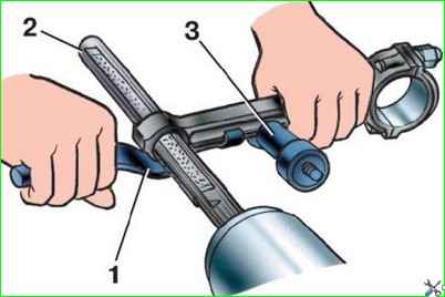
After deployment, fine-tune the hole on a special grinding head, holding the connecting rod in your hands (Fig. 1).
Set the head grinding stones using a micrometric screw to the required repair size.
Connecting rods whose holes for the bearings in the lower head have an ovality of more than 0.05 mm must be replaced.
Replacement and repair of piston pins
Repair dimensions of piston pins and kit numbers are given in table. 2. Tolerances of the main parts of the UAZ-3151 engine
To replace piston pins without pre-machining the holes in the piston and in the upper head of the connecting rod, piston pins with a diameter increased by 0.08 mm are used.
The use of pins increased by 0.12 mm and 0.20 mm requires pre-machining of the holes in the piston bosses and in the upper head of the connecting rod as described above.
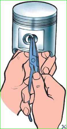
Before pressing out the piston pin, remove the piston pin retaining rings from the piston using pliers, as shown in Fig. 2.
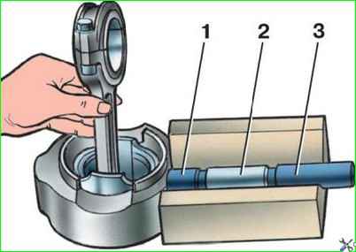
Press out and press in the pin using the device, as shown in Fig. 3.
Before pressing out the pin, heat the piston in hot water to 70°C.
Repair of piston pins consists of grinding them from large repair sizes to smaller ones or chrome plating with subsequent processing to the nominal or repair size.
Fingers with kinks, chips and cracks of any size and location, as well as traces of overheating (tarnished color) cannot be repaired.
Assembling the connecting rod and piston group
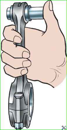
Select the piston pin to the upper head of the connecting rod with a gap of 0.0045 - 0.0095 mm.
At normal room temperature, the finger should move smoothly in the hole of the upper head of the connecting rod from the force of the thumb (Fig. 4).
The piston pin should be lightly lubricated with low-viscosity oil.
Install the finger into the piston with a tightness of 0.0025–0.0075 mm.
In practice, the piston pin is selected in such a way that at normal room temperature (20°C) it would not enter the piston due to hand effort, but when the piston is heated in hot water to a temperature of 70°C, it would enter it freely.
Therefore, before assembling, heat the piston in hot water to 70°C.
Pressing in a pin without preheating the piston will lead to damage to the surface of the holes in the piston bosses, as well as to deformation of the piston itself.
Assembling shaperform the tuna-piston group using the same device as disassembly (see Fig. 3).
To ensure proper engine balancing, the difference in weight of the pistons and connecting rods installed in the engine should not exceed 8 g.
The piston pin snap rings should sit in their grooves with slight interference. Do not use used rings.
Install the piston rings on the piston as indicated in the article - “How to replace the piston rings of a UAZ-3151.”
Given the difficulty of matching the piston pin to the piston and connecting rod (to ensure nominal fits), the pistons are supplied as spare parts assembled with the piston pin, retaining rings and piston rings.

")
")
")
")
")