Structurally, cardan transmissions of all vehicle modifications are made according to a single scheme and differ only in the number of cardan shafts and their length
Small bases of MAZ-5335 vehicles and their modifications made it possible to implement a single-cardan scheme. Below are the main data of cardan gears.
Basic data
Length of cardan shafts (distance between hinge mounting flanges) of vehicles, mm:
- - MAZ-5335, MAZ516B - 1868
- - MAZ-504V, MAZ5429, MAZ-5430, MAZ-5549 - 1320
Dimensions of cardan shaft pipes, mm:
- - outside diameter - 89±0.32
- - wall thickness - 3.5±0.16
- - diameter of the necks of the crosses, mm - 33.65-0.015
- - Type of needle bearing for cardan shaft cross GPZ-804707K3S10
For MAZ-5335 MAZ-516B vehicles, cardan shafts are longer than those of other modifications. Cardan connections of all cardan gears of MAZ vehicles are completely unified.
For MAZ-64227 vehicles, the cardan transmission consists of two cardan shafts: a drive to the middle and rear axles. MAZ-54322 has one cardan shaft to the rear axle.
Maintenance of the cardan transmission consists in performing lubrication work, as well as checking the condition of fastening of the flanges of the cardan shaft and needle bearing caps.
Possible malfunctions of the driveline and ways to eliminate them by maintenance and repair operations are shown in the table.
Gimbal lubrication is carried out in strict accordance with the frequency of lubrication operations and the lubricant used for bearings, crosses, splines.
Checking the fastening of the propeller shaft flanges is carried out on the vehicle with the parking brake released.
The gearshift lever is set to the neutral position. The car must be braked with stops placed under the wheels.
If, when swinging the flanges-forks of the driveline, a loosening of the flanges of the output shaft of the gearbox or the drive gear of the rear axle gearbox is detected, it is necessary to disconnect the corresponding end of the driveshaft, unpin the flange fastening nut, and then tighten it to failure and cotter it.
All the bolts of the cardan shaft flanges must also be carefully tightened to a torque of 44-56 Nm (4.4-5.6 kgf.m).
In the absence of a torque wrench, they must be tightened to failure. Replacing the flange bolts installed during factory assembly with non-heat-treated bolts is not allowed.
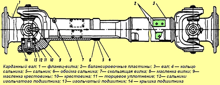
The gaps between the cross 10 and the needle bearings 13 (see Fig. 1) are eliminated by tightening the bolts securing the bearings.
|
Nominal and repair dimensions of the bearing surface for axle gear near the cup of the differential box (table 1) |
||
|---|---|---|
|
Size |
Distance from hole axes under spikes to the reference surface for axle gear, mm |
Thickness support washer, mm |
|
Rated 1st repair 2nd in 3rd . |
46.5+0.1 46.7+0.1 46.9+0.1 47.1+0.1 |
1.5-0.1 1.7-0.1 1.9-0.1 2.1-0.1 |
Malfunctions that occurred during operation and the method of elimination
Increased noise, clearly audible when coasting
- Lack of lubrication in spline - Lubricate spline
- Loosen flange yoke bolts - Tighten bolts
- Worn spline parts - Replace cardan shaft
- Intermediate Bearing Worn - Replace Bearing
Gimbal vibration
- Bent or twisted propshaft tube - Replace propshaft
- Incorrect connection of the sliding fork to the splined end of the shaft - Fit the splined end of the shaft to the sliding fork by aligning the arrows
- Increased wear on hinge parts - Replace spider
- Balancing plates torn off - Replace shaft or balance
When disassembling the cardan shaft with a sliding fork (see Fig. 1), do the following:
- - bend the antennae of the locking plate from the edges of the bolts, unscrew the bolts and remove the locking plates, covers of 14 bearings from the ends of the cheeks of the forks;
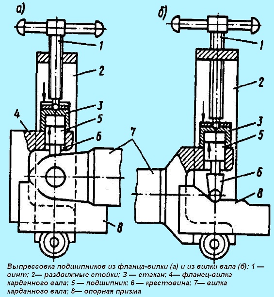
- - remove the needle bearings 13 from the holes of the yoke flange 1 and the sliding yoke 7. A special tool must be used to press the bearings out of the yoke flange and the yoke.
Do not use a hammer, as this leads to misalignment of the bearing holes in the hinge forks.
When pressing out the bearings on the support prism (Fig. 2), install the yoke 7 of the cardan shaft and press the bearings out of the yoke flange (see Fig. 2, a), then press the end seals and remove the yoke flange 4 and after that the spikes crosses 6 are installed in special holes of the support prism and the bearings are pressed out of the fork 7 of the cardan shaft (see Fig. 2, b);
- - remove the flange-fork 1 from the spikes of the cross 10 (see Fig. 1) and remove the cross 10 from the holes of the sliding fork, unscrew the oiler 9 from the cross 10.
In the same sequence, the cardan shaft is disassembled from the side of the connection with the sliding fork.
Subsequent disassembly is done in the following order:
- - unscrew the oiler 8 from the sliding fork 7;
- - unscrew the clip 6 of the stuffing box and remove the sliding fork 7 from the splined end of the cardan shaft;
- - remove the sealing ring 4 of the stuffing box from the cage 6 of the stuffing box and remove the cage 6 from the splined end of the shaft.
The yoke flange, the sliding yoke and the driveshaft cross are subject to repair in the driveline.
The flange-fork of the cardan shaft is made of steel 40 and heat-treated to a hardness of HB 229-269.
The main defects, in the presence of which the flange-yoke must be restored, are: wear of the holes for the bearings and the bolts of the flange. The flange-plug is rejected if the distance between the cheeks is less than 134.96 mm or more than 135.09 mm.
When bearing holes are worn out up to a diameter of more than 50.05 mm, they are restored by setting repair bushings.
The flange-fork with a 132 mm seat collar is installed in a fixture mounted on the lathe spindle, fixed with a clamp and two holes are bored in a line to a diameter of 53 + 0.06 mm.
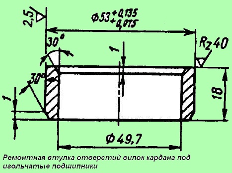
Then, repair bushings (Fig. 3) made of steel 20 are pressed into the bored holes, welded to the plug at four points from the inside with an UONI-13/45 electrode Ø 3 mm.
Then, the bushings from the side of the inner end are filed flush with the main surface of the part, the holes in the bushings are bored and reamed into a line up to Ø 50+0.027 mm.
The axis of the surfaces of the holes for the bearings of the surface must intersect the axis of the seat collar with an accuracy of 0.1 mm and the misalignment of the surfaces of the holes for the bearings is allowed no more than 0.025 mm.
When wear is more than 10.5 mm, the holes for the mounting bolts are drilled up to Ø 12 mm, countersinked at an angle of 90 ° to a depth of 8 mm and welded with an UONI-13/55 electrode Ø 4 mm.
Then, the flange is installed in the fixture on the lathe, based on the holes for the bearings, and the surface of the flange is machined on both sides from the influx of metal flush with the main surface.
After that, the flange is installed in the conductor, based on the surface of the landing collar, eight holes are drilled Ø 10+0.3+0.1 mm and countersinked from both sides (chamfer 0.5 x 90°). The holes should be evenly spaced around the circumference with an accuracy of 0.12 mm.
The sliding fork of the cardan shaft is made of steel 40 and heat-treated to a hardness of HB 229-269. The fork is restored when the holes for the bearings, spline grooves in width and outer diameter are worn out, and when the thread for the stuffing box is damaged.
The bearing holes are restored in the same way as in the yoke flange. The axes of the surfaces of the bearing holes and the splined surface must be perpendicular with an accuracy of 0.1 mm over a length of 100 mm and intersect with an accuracy of 0.1 mm
The misalignment of the surfaces of the holes for bearings is allowed no more than 0.025 mm.
When worn over an outer diameter of more than 65.05 mm or in width up to a size of more than 5.10 mm, the spline grooves are restored by compression while cutting the thread for the nut.
The propeller shaft cross is made of 18KhGT steel and cemented to a depth of 1.6—1.9 mm, followed by hardening to a hardness of HRC58—64.
The main defect in which the cross is to be restored, is the wear of the studs to a size of less than 33.62 mm.
If the distance between the ends of opposite spikes deviates to less than 126.91 mm or more than 127.05 mm, the cross is rejected.
Worn cross spikes are restored to a diameter of 36.5 by vibro-arc surfacing of OBC wires with a diameter of 1.6 mm with cooling, followed by grinding to a diameter of 33.65-0.015-0.030 mm and a roughness of 0.63.
The spikes must lie in the same plane with a deviation of no more than 0.3 mm.
The cardan shaft is assembled in the following sequence:
- a safety valve and an angle oiler 9 are screwed into the crosspiece 10 (Fig. 1), the inclined part of which should be located between the spikes of the crosspiece at an angle of 45 ± 5 ° and protrude from the crosspiece by no more than 33 mm. the size corresponds to the distance of the butt end of the oiler to the axis of the spikes of the cross;
- - insert the assembled cross with 10 spikes into the holes of the sliding fork 7 and install the fork flange 1 on the free spikes of the cross.
- - mechanical seals 11 are pressed onto the tires of the cross 10 through the holes for the bearings in the forks, grease No. 158 in the amount of (10 ± 1) g is placed into the cavity between the working edges of the mechanical seal and the needle bearing in the amount of (10 ± 1) g in each bearing;
- - press the needle bearings 13 into the holes of the fork 1 and the sliding fork 7. The assembly of the hinge with the bearings is carried out only using a manual press.
It is allowed to unscrew the oiler from the cross to facilitate the assembly of the hinges when pressing the bearings to release excess grease, and the greaser should be screwed in after the hinge is fully assembled;
- - install support and locking plates on the ends of the cheeks of the forks, fix each cover and plates with bolts, which must be tightened to a torque of 14 ... 17 Nm (1.4-1.7 kgf / m) and locked by bending one of the ears locking plate to the face of the head of each bolt;
- - similarly install the flange-plug from the second end of the cardan shaft 3;
- - from the side of the splined end, the cage 6 of the stuffing box 5 of the sliding fork 7, the ring 4 of the stuffing box are installed, laying it in the cage, and the sealing rubber ring 4 is filled into the cage;
- - install a sliding fork 7 on the splined end of the cardan shaft so that the axes of the holes in the sliding fork and in the fork on the shaft 3 are in the same plane, the deviation of the axes of these holes by an angle of not more than 2 ° is allowed.
In this case, the arrows on the sliding fork and the cardan shaft pipe must be aligned;
- - screw the gland 6 of the stuffing box onto the sliding fork 7, screw the oiler 8 into the fork and lubricate the spline connection with USSA or Litol-24 grease through it until it is squeezed out of the hole of the sliding fork plug;
- - core clip 6 of the gland of the sliding fork in two places located along the circumference;
- - check the swing angle of the cardans from the middle axis in each direction, which must be at least 24 °;
- - perform dynamic balancing of the assembled cardan shaft.
- - imbalance should not exceed 65 gsm. the imbalance is eliminated by welding plates 2, bent along the outer diameter of the cardan shaft, and turning the sliding fork by 180°.


