To increase the liter power in the KamAZ-7403.10 engine, supercharging is used, i.e. air is supplied to the cylinders using a compressor under pressure 1.5-1.9 times higher than atmospheric
This made it possible to increase the mass of air supplied to each cylinder, and, consequently, to burn increased doses of fuel in the cylinders.
With the same engine dimensions, crankshaft rotation speed and number of cylinders, its power during supercharging increased to 191 kW (by 24%).
Technical characteristics of the TKR7N turbocharger
Air supply range through the compressor 0.05-0.2 kg/s
Boost pressure (excess) at rated engine power, 1 kPa (kgf/cm 2) 54-83.4 (0.55-0.85)
Rotor speed at rated engine power, min -1 80,000-85,000
Temperature of gases at the turbine inlet, °C:
- - during long-term operation, no more than 650
- - for short-term operation (up to 1 hour), no more than 700
Lubricating oil pressure at the inlet to the turbocharger, kPa (kgf/cm 2):
- - on the engine under load 196.2-392.4 (2-4);
- - on the engine without load, not less than 98.1 (1)
Due to the use of turbocharging, the basic design of the KamAZ-740.10 engine has undergone minor changes.
The compression ratio is reduced to 16 by changing the shape of the combustion chamber in the piston crown.
The pistons for a turbocharged engine use a cylindrical combustion chamber instead of a toroidal one, i.e. without a displacer, with a larger diameter and depth.
This made it possible to increase the volume of the combustion chamber, but the pistons became non-interchangeable with those used on the base engine model.
The fuel equipment of the turbocharged engine has undergone the following changes: a model 334 injection pump has been installed, adjusted to cyclic fuel supply (96 mm 3/cycle); model 271 injectors are used with the diameter of the spray holes increased to 0.32 mm and increased pressure at the start of fuel injection.
Two turbochargers provide air pressure into the cylinders.
One turbocharger serves the left bank of cylinders, the other serves the right bank. They operate using the energy of exhaust gases.
Usually the energy of the exhaust gases is lost, and in a turbocharger some of it is used for operation. As a result, with increasing power, specific fuel consumption decreases.
Turbochargers are installed on the exhaust manifold pipes so that the rotor axis is perpendicular to the axis of the crankshaft.
The exhaust manifolds are made of solid cast iron.
Special spherical washers are installed under the exhaust manifold mounting bolts, which compensate for the angular movements of the bolts when the manifold is heated relative to the cylinder heads; The fastening bolts are secured with folding plates to prevent them from being turned out.
To seal the gas joint between the manifold and the cylinder heads, gaskets made of asbestos steel edged with a metal sheet are installed, and the seal of the joint between the exhaust manifold and the pipe is ensured by a gasket made of heat-resistant steel sheet, as well as the joint between the compressor and the pipe.
The intake system of the KamAZ-7403.10 engine differs from the intake system of the base KamAZ-740.10 engine in the presence of additional pipes, a modified design of the intake manifolds and a different connection point for the air cleaner clogging indicator.
Combining the intake manifolds of each row of cylinders with a pipe helps reduce the amplitude of pressure fluctuations in the intake manifold and reduce their harmful effects on the operation of the turbocharger.
The turbocharger bearings are lubricated by circulation under pressure from the engine lubrication system. The oil is drained into the engine crankcase.
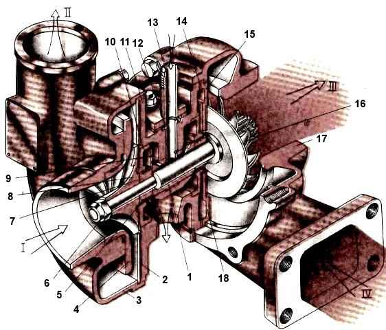
The main parts of the turbocharger are the bearing housing 11 (Fig. 1), the compressor housing 3, the turbine housing 17 and the rotor, consisting of a shaft with a turbine wheel 16 welded to it on one side and a compressor wheel 8 secured to the shaft with a nut 6.
Hot exhaust gases leaving the cylinders enter the housing 17 under pressure through the manifold and, expanding in the interblade space, the turbine wheel 16 rotates at a very high frequency (up to 85,000 rpm); gases escape into the atmosphere through the exhaust pipe and muffler.
The rotor shaft rotates the compressor wheel 8, which sucks air from the atmosphere through the air cleaner, compresses it and pumps it into the engine manifold. Under excess pressure, air enters the engine cylinders.
Since the temperature of the exhaust gases at the turbine inlet reaches 700 °C, the turbine wheel is cast from a heat-resistant alloy, and its body is made from cast iron.
To reduce heat transfer from the turbine housing to the bearing housing, a cast iron screen 15 and an asbestos steel gasket 14 are installed between them.
At high rotation speeds, rolling bearings do not operate reliably, so the turbocharger uses plain bearing 1, made of the “oscillating bushing” type and installed in the housing bore 11 with a gap of up to 0.1 mm.
Oil is pumped into this gap, which serves as a liquid cushion that dampens vibration.
The bushing is held against axial displacement and rotation in the housing by clamp 12, through which oil is pumped from the main line of the engine.
The oil, passing through the gaps along the bearing and its channels, enters the drain cavity of the bearing housing and then into the engine crankcase.
Under pressure, oil from the bearing assembly tends to flow into the flow part of the compressor, and oil leaks increase with increasing air rarefaction on the compressor side.
To prevent oil from entering the compressor flow path, a contact seal is used between the oil deflector 7 and the cover 10, which consists of two piston-type cast iron sealing rings 5 installed in the grooves of the oil deflector.
The seal includes an oil discharge screen 9, designed to separate the cavity of the sealing rings from the drain cavity of the bearing housing.
On the turbine side there is a similar contact seal without an oil discharge screen, but here the sealing rings operate with gas back pressure in all diesel modes, which reduces the possibility of oil leakage.
However, these rings operate at higher temperatures, which creates the risk of coking of the grooves and loss of ring mobility. This is possible when the engine suddenly stops while it is working on the load.
If, before stopping the engine, you let it run for 3-5 minutes at idle speed, then an increased temperature in the area of the sealing rings is not observed, which means that coking of the oil in the rotor grooves does not occur.
The turbocharger is the lubrication point furthest from the oil pump.
This circumstance requires compliance with certain conditions for starting and warming up the engine, especially at negative ambient temperatures.
At the moment the engine starts, the oil pump supplies oil to the turbocharger bearings with a certain time delay caused by the hydrodynamic resistance of the pipelines on the suction line of the oil pump and the channels on the oil discharge line.
A delay in the flow of oil changes the hydrodynamic operating conditions of the bearing assembly, which, if the diesel engine warm-up mode is violated after start-up, can lead to failure of the turbocharger.
To avoid failure, the engine is warmed up at a crankshaft speed of less than 1500 rpm until the oil pressure in the lubrication system rises above 100 kPa (1 kgf/cm 2 on the pressure gauge) .
After changing the oil in the engine crankcase and the filter elements of the full-flow filter, it is recommended to turn the crankshaft before starting with the starter for 10-15 seconds with the fuel supply turned off.
When pressure appears in the main oil line, determined by the pressure gauge, you can start the engine.
Research has shown that when the engine is idling, the vacuum in front of the contact seal rings behind the compressor wheel reaches a maximum value, which contributes to oil leakage into the compressor flow path and further into the engine cylinders.
Prolonged operation of the engine in idle mode causes the formation of blue smoke in the exhaust, increased oil consumption, and carbon deposits on the turbine flow path.
To avoid these malfunctions, for example when pumping air into the brake system reservoirs, it is recommended to maintain the crankshaft speed within 1200-1600 rpm.

")
")
")
")
")