The electric torch device (EFD) is designed to facilitate starting a cold engine at ambient temperatures down to -30 °C
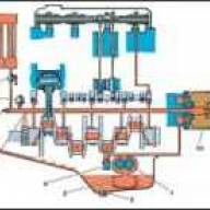
Conventionally, the electric flare system can be divided into two interconnected ones: fuel and electric.
The fuel system also provides the dosage of diesel fuel for combustion.
It is connected to the engine fuel supply system.
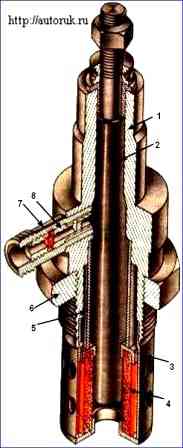
The main element of an electric torch device is torch candles.
They are installed in the engine intake pipes so as to ensure a uniform supply of heated air and fuel vapor to all cylinders.
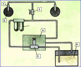
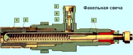
The body 1 of the flare plug (Fig. 1) is of a non-separable design, has a lower threaded part for screwing into the inlet pipeline and fixing it on it with a lock nut 6.
Heating element 2 is made in the form of a pin candle and is a metal casing, inside of which a spiral is pressed into a special filler.
The filler has good thermal conductivity and electrically insulates the spiral from the casing.
The heating element heats the spark plug to operating temperature, which ensures evaporation and ignition of diesel fuel.
Fuel comes from the power system to the fitting, where it is cleaned by filter 7, and then enters the annular cavity formed by the surface of the heating element and the evaporator 5. The amount of fuel is dosed by jet 8.
To increase the evaporation surface, a volumetric mesh 4 is used, surrounded by a screen 3 with two rows of holes.
The screen protects the flame from being disrupted by the flow of air sucked into the engine cylinders.
The operating principle of the electric torch deviceis as follows
Before starting the engine, excess fuel pressure is created using a manual fuel pump, which is maintained by the fuel pump while the crankshaft is cranked by the starter.
The fine filter nozzle valve and the injection pump bypass valve, blocking the drainage fuel lines, ensure the supply of fuel to the flare spark plugs 13 with a minimum time delay under a pressure of 20-40 kPa.
At this pressure, the minimum time for the formation of a flame is ensured.
An increase or decrease in this pressure leads to a delay in the formation of the torch and, accordingly, to an increase in the start-up time.
The fuel passes through the solenoid valve 11 and reaches the preheated flare plugs, where it is dosed, heated and evaporated.
The ignition of the fuel and the formation of a flame occurs due to the fact that at this moment the engine crankshaft is cranked by the starter and an air flow appears in the intake pipes, blowing the flare plugs.
Particles of fuel that did not burn in the intake pipes in the form of vapors enter the cylinders along with the heated air, where they ignite and contribute to the ignition of the main fuel injected through the injectors.
To reduce the time it takes for the engine to reach a stable mode, it is possible to combine its operation with the operation of an electric torch device.
This ensures stable retention of the torch in all intake pipelines when the engine is idling.
Technical characteristics of EFU products
Torch candle:
- - rated voltage, V - 19
- - current consumption at rated voltage, A 11-11.8
- - fuel throughput, cm3/min 5.5-6.5
Thermal relay:
- - rated voltage, V - 24
- - rated current Ampere - 22.8
- - time from the moment the current is turned on until the contacts close, s 50-65
- - time of closed state of contacts after turning off the current, s > 45
Solenoid valve:
- - rated voltage, V - 24
- - switching voltage (opening), V >12
- - shutdown (closing) voltage, V >6
- - current consumption at voltage 12 V, A <1.1
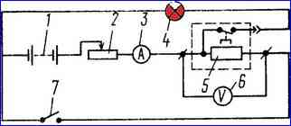
Electrical diagram
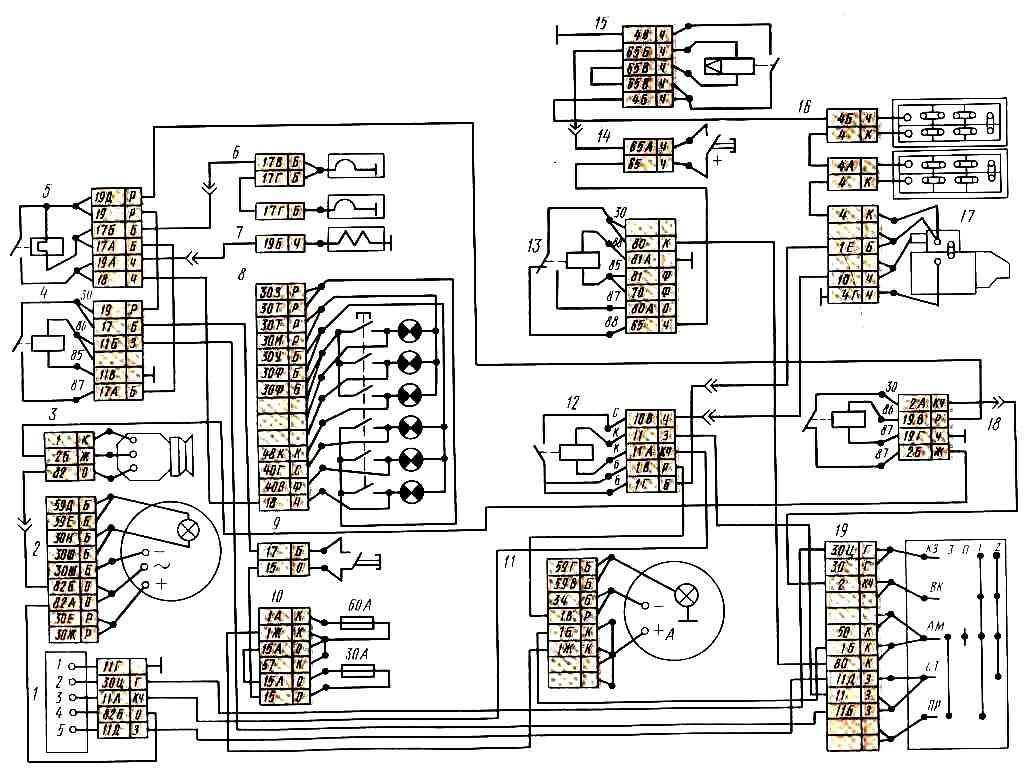
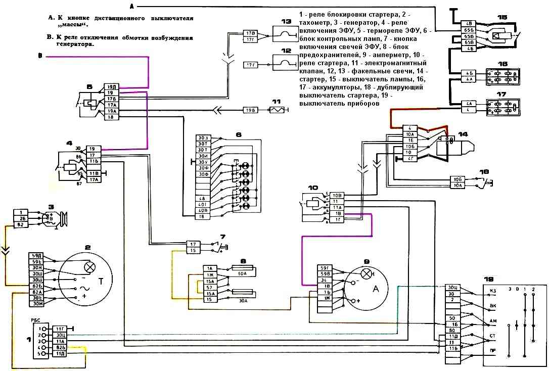
The ECU is powered by the car's batteries and includes torch spark plugs 6 (Figure 2), a thermal relay 5, which serves to turn on the electromagnetic fuel valve 7, and a control lamp of the unit 8, signaling that the spark plugs are sufficiently heated and power is supplied to solenoid valve; relay 4, designed to turn on the spark plugs for maximum heating; relay 18 disconnects the generator excitation winding for the period of operation of the electronic control unit.
To activate the electronic control unit, you need to press button 14 for remote switching on the mass, then press button 9 and hold it in this position until the lamp in block 8 lights up, then turn on the starter by turning the key switch 19 to the second position without releasing button 9.
The ECU is powered from batteries by turning on button 14 along the circuit: “+” batteries - starter terminals 17 - starter relay 12 - ammeter - instrument and starter switch 19 - heater motor relay 13 - button 14 - switch winding - 15 ground — “—” batteries.
Switch 15 is activated and connects the “—” batteries to the vehicle ground.
It should be borne in mind that you cannot keep button 14 pressed for more than 2 s, since otherwise the winding of the electromagnet of switch 15 may overheat.
The normally closed contacts of relay 13 of the electric motors of the cabin heater are used to supply current to the winding of the electromagnet of switch 15. This is done to prevent the possibility of disconnecting the batteries
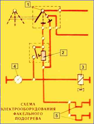
Simplified EPI connection diagrams (to make it easier to understand how the electric torch device works):
Possible malfunctions of the EPU and methods of elimination
Fault
- Cause of malfunction
Elimination method
Voltmeter needle at the lower limit of the scale
- Closing the thermal relay spiral or electrical wires
If the spark plugs are in good condition, disconnect the wire connecting it to the ECU power button from the thermal relay.
The absence of a change in the arrow readings indicates the closure of the thermal relay spiral. In this case, the thermal relay should be replaced.
If the thermal relay spiral is intact (determined by touch) and the position of the arrow does not change when the wires are disconnected from the spark plugs, then this indicates a short circuit in the electrical wires.
Remove short circuit.
- Shorting the spark plug to ground
Disconnect the wire from the left spark plug terminal, eliminating contact of the tip with ground, and turn on the EPI again. When the arrow goes beyond the scale, disconnect the wire from the right spark plug terminal.
The absence of the arrow going beyond the scale indicates the closure of the right candle. Replace the failed spark plug.
After eliminating the short circuit, it is recommended to check the condition of the insulation of the electrical wires, the operability of the thermal relay and the ECU turn-on relay, and if a short circuit occurs when starting the engine, the operability of the shunt relay
The voltmeter reading does not change
- Thermal relay burnout
Turn on the ECU and check the voltage at the thermal relay terminals. The absence of voltage at the terminal on the side of the plug connection and the presence of voltage at the other terminal indicates burnout of the spiral.
Replace the thermostat
- Burnt out spark plugs or lack of contact in the circuit
Turn on the EPI and check for voltage at the terminals of each EPI product, starting with the flare spark plugs. The presence of voltage at the terminal of the right spark plug indicates burnout of the spark plugs. Replace the spark plug and restore contact
- One of the candles burns out
Turn on the EPU for 10-15 seconds, then replace the cold spark plug
No candle torch
- Lack of receipt fuel to spark plug
Loosen the fuel supply fitting on the spark plug.
Turn on the ECU and after the indicator lights up (opening of the solenoid valve), turn the crankshaft using the starter.
If fuel does not leak through a loose threaded connection of the fitting when the valve is open, troubleshoot the fuel supply system
- Failure of fuel to pass through the spark plug
Unscrew the spark plug from the manifold.
Rinse and blow out the nozzle, fuel filter and fuel supply cavities with compressed air.
Check for presence of torch flame
- Leakage of the fuel supply system
Remove leaks
Checking the operation of the EFU
The operation of the EPI should be checked with serviceable and charged batteries in the following order:
- - check the serviceability of the ECU indicator on the instrument panel in the cockpit (by pressing the control button);
- - turn on the EPI and determine the time when the EPI is turned on before the indicator lights up.
To turn on the EFU for the first time, it should be 50-70 seconds at an air temperature above zero, and 70-110 seconds at a temperature below zero.
When the EPI is turned on again, the time the indicator lights up is reduced, therefore, to obtain a reliable value, it is necessary to allow the thermostat to cool to ambient temperature:
- - check for the presence of a torch flame in the intake manifolds.
To check the torch you need:
- - unscrew the spark plugs from the manifolds, connect fuel pipes and electrical wires to them;
- - ensure a reliable connection of the spark plug housings to the ground and make sure that the terminal is isolated from the ground;
- - turn on the ECU and after the indicator lights up, use the starter to turn the crankshaft.
If there is no flame, replace the faulty spark plug.
Determine the performance of relay 4 for turning on the EPI in the following order:
- - disconnect any wire from terminal “K” of the additional starter relay;
- - press the ECU power button and turn the instrument and starter switch key two or three times for no more than 1 second to position II (far right position). If the relay is working properly, you should hear characteristic clicks;
- - turn off the EFU and connect the wire to terminal “K”.
Determine the performance of the OVG shutdown relay as follows:
- - press the ECU button and start the engine with the starter. When the engine speed changes over the entire range, the ammeter needle should show a discharge current of about 30 A. Stop the engine and only then release the ECU button;
- - start the engine again and make sure that the generator is charging.
Note. When preparing the car for the first winter operation, additionally check the fuel supply to the ECU spark plugs and the throughput of the spark plugs.
EFU repair
Electric torch device products cannot be repaired; If a product failure is detected, replace it.
To check the fuel supply to the spark plugs, disconnect the fuel line from the spark plugs and bleed the engine supply system with fuel using a manual fuel priming pump.
Then open the solenoid valve by applying voltage to the valve plug from the engine compartment lamp wire plug.
In this case, fuel should appear from the disconnected fuel line.
Determine the throughput of the spark plug on domestic stands SDTA-3 (KI-22201) or NC-108-1318 from Mo1ogra1, Czechoslovakia and others, which allow you to smoothly regulate the fuel pressure.
At an excess pressure of diesel fuel of 73.6 kPa (0.75 kgf/cm 2) and a temperature of 15-25°C, the throughput of the spark plug should be 5.5-6.5 cm 3/min.
Make measurements after first pouring fuel onto the spark plug for 20-30 seconds.
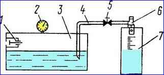
If there is no From the indicated stands, assemble the installation according to the diagram in Fig. 5.
To determine the amount of current consumed by the spark plug assemble a circuit (Fig. 6) that allows you to have a DC output voltage of 19 V.
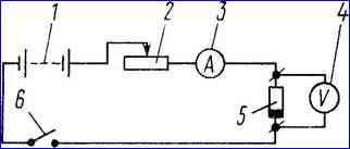
Maintain the voltage with rheostat 2. At this voltage, the current consumption a minute after turning on the spark plug should be 11-11.8 A.
To check the parameters of the thermal relay assemble the circuit shown in Fig. 7.
Install the thermostat on a horizontal surface with the protective screen facing up.
Set and maintain the nominal current value of 22.8 A passing through the relay with rheostat 2.
Determine the time before the contacts close and hold them in the closed state by the lightning of the control lamp 4. To do this, connect one wire of the control lamp to the thermal relay plug, and the second to a DC source (battery).
The time from the moment the current is turned on until the thermal relay contacts close (the control lamp lights up) at an ambient temperature of 15-25 ° C should be 55-65 seconds, and the contact holding time (the control lamp lights up) after disconnection should be at least 45 seconds.
Check the tightness of the solenoid valve by supplying compressed air under a pressure of 147 kPa (1.5 kgf/cm 2) to the valve inlet channel.
When the valve is immersed in water, no air bubbles should be released
Maintenance
With service “C” (autumn):
- - wash the spark plugs and free the ECU fuel lines from summer fuel (after replacing the fuel in the power system with winter fuel);
- - check the operation of the EFU.
When washing the EFU spark plugs, clean the protective sleeve 1 (Fig. 10) and mesh 2 from deposits, then rinse them with gasoline.
To free the ECU fuel lines from summer fuel after replacing it with winter fuel in the electric motor power system:
- - start the engine and let it run at medium crankshaft speed until the remaining summer fuel from the power system is completely exhausted;
- - stop the engine and disconnect the fuel lines from the spark plugs;
- - open the solenoid valve by applying voltage to its plug from the plug of the engine compartment lamp wire. The weight of the vehicle must be included. The opening of the valve is accompanied by a characteristic click;
- - bleed the engine power system with a manual fuel priming pump until summer fuel drains from the ECU fuel lines;
- - connect the fuel lines.

")
")
")
")
")