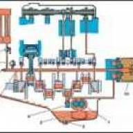
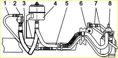
The steering (Fig. 1) consists of a steering wheel, a steering column with a casing, a universal joint, a steering mechanism, a power hydraulic cylinder, a power steering pump, pipelines with hoses, longitudinal and transverse steering rods
The steering column 15 is attached with a stepladder 14 to the body bracket. Rotation torque of steering column shaft 16 – (0.3-0.8) Nm.
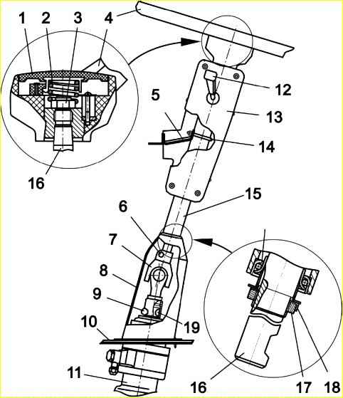
The axial clearance in the steering column bearings is adjusted using nut 17.
After adjustment, the nut is locked with the washer by bending it onto the edge of the nut. Nut 3 of the steering wheel fastening is locked by punching at two opposite points.
The steering mechanism (Fig. 2) consists of a housing, a screw with a ball rack nut and a gear sector.
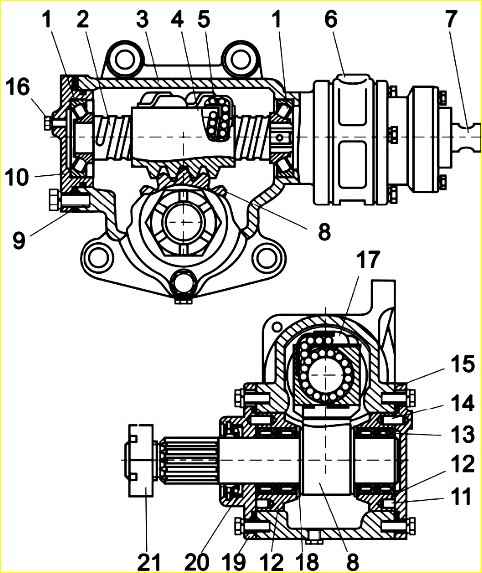
The steering gear ratio is 23.6.
The screw rotates in two angular contact spherical bearings, the clearance in which is adjusted by spacers 9.
A distributor is installed at the upper end of the crankcase and the screw shank, designed to distribute working fluid under pressure into the working cavities of the power cylinder during wheel control.
The power hydraulic cylinder (Fig. 3) is designed to create force on the bipod of the steering mechanism.
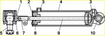
The power cylinder is secured with a rear support to the base bracket with a cylindrical pin installed in the hinge.
The hinged tip is attached through ball pin 5 to the upper arm of the bipod with a nut that is cottered.
Attention! If the wheels hit an obstacle strongly, the force developed by the power cylinder may not be enough to keep the wheels from turning, and then the driver will feel a twisting shock on the steering wheel.
The gear-type power steering pump is driven by the engine timing gears.
Before operating the bus at subzero outside temperatures, the working fluid must be warmed up at engine idle speed without pump load.
The oil tank (Fig. 4) has a replaceable filter element 4 mod. FGM 620-1.
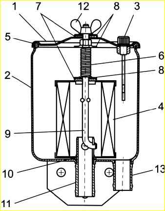
Rubber 7 and metal 8 washers are placed on top of the pin 9, which are used as a safety valve.
If adjustment fails to reduce the excessive clearance in the joint, the pin with liners or the tip assembly should be replaced.
The lid is sealed along the contour with cuff 5.
The liquid level indicator probe 3 with the “min” and “max” marks is screwed into the cover sleeve.
Attention! In the event of failure of the power steering, transportation Passengers are prohibited. It is allowed to move to the repair site (to the vehicle depot) subject to safety precautions.
The steering rod is tubular, with threaded ends onto which ends with hinges are screwed.
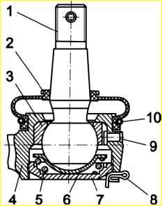
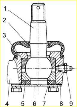
Tie rod ends can be adjustable (Fig. 5) or non-adjustable (Fig. 6).
During daily maintenance of the steering, the free play of the steering wheel is checked, as well as the tightness of the connections and pipelines of the hydraulic booster.
Checking the free play of the steering wheel should be done with the engine idling, with the steering wheels installed directly, rocking the steering wheel in one direction or the other until the steering wheels begin to turn.
The free play of the steering wheel should not exceed 20°, which corresponds to a movement of the steering wheel rim of approximately 80 mm.
If the free play of the steering wheel is more than permissible, then it is necessary to check the condition of the steering rod joints, the fastening of the steering gear housing, the clearance in the universal joint of the steering shaft and its fastening, check the adjustment of the front wheel hub bearings, the condition of the pivot assembly, and adjust the steering mechanism .
If there is a gap in the tie rod joint, it should be adjusted, if the tip is adjustable, or replaced.
To adjust the tie rod joint, remove the cotter pin 8 (Fig. 6) and screw the plug 7 into the tip until it stops, and then turn it out to the first position for the cotter pin, but not less than 1/8 of a turn.
Re-use of the cotter pin is not permitted.
After assembling and adjusting the hinge, you need to check the moments required for rotation and swing of the ball pin.
These moments should be no more than 40 Nm. Before measuring the torque, you need to turn the ball pin two or three times by hand in both directions.
Operation of hinges in which the moment of rotation and swing of the ball pins from one extreme position to another is more than specified, can lead to breakage of the pins.
To measure torque, a special attachment is screwed onto the threaded end of the ball pin, which has places to grip a torque wrench in the horizontal and vertical planes.
After adjusting the gaps, it is necessary to hang the front wheels of the car and, with the engine not running, make sure that there is no noticeable increase in force on the steering wheel when turning it from one extreme position to another.
During maintenance, the fastenings of the steering wheel, steering column, telescopic shaft, steering mechanism, steering bipod, power cylinder, power pump, pipelines, steering rods are checked, the oil level in the power steering tank is checked, and the steering rod joints are lubricated.
In this case, attention is paid to the condition of the steering components and parts.
The cotter pin of the steering bipod nut, the telescopic shaft wedge nut, the steering knuckle nuts, and the ball pin nuts are not allowed to be missing or damaged.
The protective covers of the ball pins must not be damaged.
Maintenance of the power steering system requires special cleanliness of parts and working fluid.
During operation, it is necessary to prevent contamination of the hydraulic system, as this leads to increased wear of the pump and movable seals, as well as to overheating of the hydraulic system due to difficulty draining oil into the pump reservoir.
The tie rod joint is lubricated through a grease nipple. The grease fitting is screwed into the rod end instead of the KG 1/8" plug.
Lubricate until fresh grease is squeezed out from under the cover.
If, during the process of replenishing lubricant, the boot does not allow it to pass through, then to prevent damage to the boot, lubrication should be stopped after the cavity of the boot is filled with lubricant, which is determined by an increase in its elasticity.
After lubrication, you need to put the plugs back in place.
Checking the oil level in the tank is done using a dipstick, which is unscrewed from the tank cap. The oil level should be between the "max" and "min" dipstick marks.
If necessary, add oil to the markki "max" on the probe.
It is not allowed to operate the hydraulic booster with a low oil level in the pump reservoir, as this leads to foaming of the oil and increased wear of the pump.
The first change of oil and filter in the pump reservoir is carried out after flushing the hydraulic system during the first maintenance-1.
Subsequent oil and filter changes are carried out once a year during seasonal maintenance, or after 64,000 km.
It is recommended to replace the filter (mod. FGM-620-1) when the pressure difference at the inlet and outlet of the tank increases to 0.15 MPa, at a flow rate of 28 dm 3/min and a viscosity of the working fluid of 35 cSt.
If the filter is clogged in winter, when starting the engine, the drain hose may break or be destroyed.
To avoid overheating of the oil in the system, avoid holding the steering wheel in extreme positions for more than (8-10) seconds.
Oil overheating above 100 °C leads to a decrease in the lubricating qualities of the oil, increased wear and failure of rubber seals due to loss of elasticity.
Changing the oil in the power steering system
- Raise the front wheels of the bus and remove the power steering pump reservoir cap.
- Unscrew the plug of the lower cover of the steering mechanism, and after the oil has flowed out of the system, smoothly turn the steering wheel from lock to lock (5-6) times.
- Replace the filter and clean the bottom of the tank.
Replacing the filter element
- Unscrew nut 12 securing the tank cover (Fig. 5), remove washers 8, 7 and cover 1.
- Press the pin 9, remove the curved end of the pin from the hole in the fitting 11 and remove the pin with the spring from the tank.
- Remove the used filter element, install a new one and assemble the tank in reverse order, tightening nut 12 to a torque of (7-10) Nm.
- Fill the hydraulic system with fresh fluid.
Filling working fluid
- Tighten the plug in the steering gear cover.
- Unscrew nut 12, (Fig. 5) remove cover 1 with washers.
- Fill in the working fluid (the filling volume of the power steering system is 4.5 liters) so that the fluid level does not reach the top of tank 2 by approximately (30-40) mm.
- Check whether the end of the stud 9 is installed in one of the four holes of the fitting 11, install the sealing collar on the edge of the tank body, put the cover 1, washers 7, 8, nut 12 on the stud, tighten it by hand (torque (7-10 ) Nm).
- Start the engine and bleed the hydraulic system at low crankshaft speed, turning the steering wheel (2-3) times in both directions until it stops, without delaying in the extreme positions at idle speed.
- Check the fluid level using dipstick 3. If necessary, remove the cap and add liquid to the "max" level.
- Remove drops of oil from the outer surface of the tank.
Pumping is considered complete if the decrease in oil in the tank during pumping has stopped.
Tighten the wing nut only by hand. If there is an oil leak from under the cover, replace sealing collar 5.
Possible steering malfunctions and solutions
- Cause of malfunction
Remedy
Note: before determining the cause of the malfunction, you should check the tire pressure and steering linkage adjustment
The bus doesn't handle the road well
- There are high friction losses in the steering rod joints and king pins
Lubricate the king pins and steering rod joints
- Incorrect installation of the front wheels
Adjust and check the toe and angles of the front wheels
- Increased free play of the steering wheel
Determine the cause of the increased free play, make adjustments or replace worn parts
- Great imbalance of the front wheels
Balance the wheels
- The nut of the steering gear distributor thrust bearings is loose
Adjust the tightening of the nut
The bus constantly deviates away from the given direction
- Incorrect installation of bus axles relative to its longitudinal axis
Check the installation of bus axles, compare the size of the base on the right and left
- Brake fault in one of the front wheels
Check the brakes and fix the problem
- Violation of the hydraulic balance of the steering mechanism
Disassemble the steering gear distributor and check whether the hole in the distributor is clogged, check the mobility of the spool and plungers
Increased free play of the steering wheel
- Wear of steering rod joints or ball pins
Replace worn parts
- The fastening is loose steering propeller shaft
Tighten the driveshaft mounting wedges and threaded fasteners
- Increased gear gap
Adjust the engagement
- The distributor thrust bearing nut is loose
Adjust tightening
- Wear of the ball pair of the steering mechanism (axial movement of the screw relative to the rack nut is more than 0.3 mm)
Replace the ball pair
- Wear of driveshaft parts
Replace the driveshaft
The power steering does not provide enough force or its operation is uneven
- Insufficient oil level in the tank.
Add oil to the required level.
- Presence of air in the system (foam in the tank, cloudy oil).
Remove air. If air is not removed, check the tightness of all connections, the tightness of the suction tubes of the tank and pump, and the condition of the filter. If all of the above is correct, change the oil and filter element.
- Excessive tension in the gearing of the steering mechanism
Adjust the engagement
- Pump malfunction
Check pump
- Pump bypass valve stuck
Check valve mobility
- The distributor thrust bearing nut is loose
Adjust tightening
Lack of gain when turning the steering wheel in various engine operating modes
- The pump safety valve seat has come loose.
Disassemble the pump, tighten the seat
- Pump bypass valve stuck
Disassemble the pump and check valve mobility
Increased noise during pump operation
- Insufficient oil level in the pump reservoir
Add oil
- Clogged or incorrectly installed filter
Check installation or replace filter
- Presence of air in the system (foam in the tank, cloudy oil)
Bleed air or change oil
- Wear of pump parts
Replace the pump
Steering jams when turning
- Seized spool or distributor plungers
Disassemble the distributor and check the mobility of the spool and plungers
Knock in the steering mechanism
- The gap in the steering gear gear has been increased
Adjust the engagement
- The steering driveshaft is loose
Tighten the driveshaft mounting wedges and threaded fasteners
Ejecting oil through the reservoir breather (in the oil dipstick)
- Excessively high oil level
Set normal oil level
- The filter is clogged or incorrectly installed
Check the filter installation or replace it
- Availability of air in the system
Remove air by bleeding the system
Occurrence of steering wheel vibrations at driving speed (60-70) km/h
- Loosening of the steering mechanism, tightening of the steering levers, improper adjustment of the front wheel hub bearings (increased play), wear of the pin bushings, deformation of the discs or excessive imbalance of the steering wheels
Tighten the steering components and adjust the front wheel hub bearings. Rearrange the wheel rims on the studs by (60-180)° or balance the front wheels.

")
")
")
")
")