Requirements for parts and assemblies of the D-245 diesel engine
The cylinder block is the main body part of a diesel engine and is a hard cast iron casting.
There are four removable sleeves made of special cast iron in the vertical bores of the block.
The sleeve is installed in the cylinder block along two centering belts: upper and lower.

In the upper belt, the sleeve is fixed with a shoulder, in the lower belt it is sealed with two rubber rings placed in the grooves of the cylinder block.
The sleeves are sorted by inner diameter into three size groups: large (B), medium (C) and small (M).
The group marking is applied on the end face of the sleeve shoulder. On a diesel engine, sleeves of the same size group are installed.
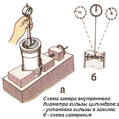
Scheme for measuring the inner diameter of the cylinder liner is shown in fig. 2.
Coolant circulates between the walls of the cylinder block and the liners.
The end walls and transverse partitions of the cylinder block in the lower part have tides designed to form the upper supports of the crankshaft.
These bosses are fitted with covers that serve as lower crankshaft bearings. The tides, together with the covers, form beds for the main bearings.
The beds for the main bearing shells are bored together with the main bearing caps, so the caps cannot be interchanged.
The cylinder block has a longitudinal channel, from which oil flows through the transverse channels to the crankshaft main bearings and camshaft bearings.
The cylinder block in the second and fourth upper bearings of the crankshaft has nozzles that serve to cool the pistons with a jet of oil.
On the outer surfaces of the cylinder block there are machined mating surfaces for mounting a centrifugal oil filter, a liquid pump, a fine fuel filter, an oil filler neck
The flatness of the upper surface of the cylinder block must not exceed 0.15 mm (0.05 mm for a new block).
The diameter of the holes in the cylinder block for the main bearing shells when tightening the cap bolts with a torque of 190 ... 210 Nm should be 81 + 0022 mm.
When the surfaces of the main bearings are worn up to a diameter of more than 81.03 mm, it is recommended to restore the bushing to a larger outer diameter.
Inverting and rearranging the main bearing caps is not allowed.
The surface roughness of the holes for the main bearing shells should be Ra≤0.63 µm.
The difference between the depths of the bores for the cylinder liner shoulder should not exceed 0.04 mm.
Oil channel openings must be free of dirt.
The cavity of the cylinder block, washed by the coolant, and the oil channels must be checked for tightness with water at a pressure of at least 0.4 MPa for 1 minute. Coating of raw surfaces should be done with a primer.
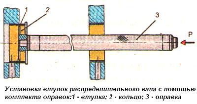
When pressing the front, middle and rear bushings of the camshaft, the oil holes in the bushing and block must match.
The rear bushing of the camshaft must be pressed into the block to a depth of 7 mm relative to the rear plane, and the front bushing should be flush with the front plane of the block.
The bushings must be pressed in using a set of special mandrels (Fig. 3).
The deviation from the flatness of the mating surface of the oil sump should not exceed 0.25 mm.
When testing the oil sump with a liquid under a pressure of at least 0.1 MPa, no leaks or drops appear over the entire surface.
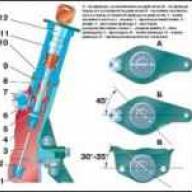
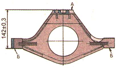
The deviation from the flatness of the surfaces "A" and (Fig. 4) of the front support of the diesel engine should not exceed 0.1 mm.
The deviation from the parallelism of the surfaces "B" relative to the surface "A" should not exceed 0.2 mm over a length of 100 mm.
The "B" surfaces must lie in the same plane; allowed
The riveted part of the limiter should not protrude above the plane of the shock absorber plate by more than 0.5 mm.
The shock absorber rubber should not have cracks or tears.
When the shock absorber is compressed with a force of 2 kN, its deformation in height should be 2.5 ± 0.5 mm.
Mounting interfaces of body parts

The main parts of the crank mechanism are: crankshaft 5, pistons 11 with piston rings and pins, connecting rods 8, main and connecting rod bearings, flywheel 15.
The crankshaft is steel, has five main and four connecting rod journals.
In the connecting rod journals of the crankshaft there are cavities for additional centrifugal oil cleaning. The cavities of the necks are closed with threaded plugs.
The axial force of the crankshaft is perceived by four semi-rings 14 made of aluminum alloy, installed in the bores of the cylinder block and the fifth main bearing cap.
To reduce the load on the bearings from inertial forces, counterweights 7 are installed on the first, fourth, fifth and eighth cheeks of the crankshaft. Front and rear, the crankshaft is sealed with cuffs.
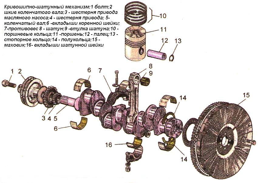
At the front end of the shaft, gear 4 of the gas distribution drive, gear 3 of the oil pump drive, pulley 2 of the drive of the liquid pump and generator are installed. A flywheel 15 is attached to the rear flange of the shaft.
The crankshaft can be manufactured and installed on a diesel engine of two production sizes (nominals).
The crankshaft, the connecting rod or main journals of which are made according to the size of the second denomination, has an additional marking on the first cheek.
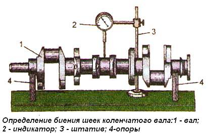
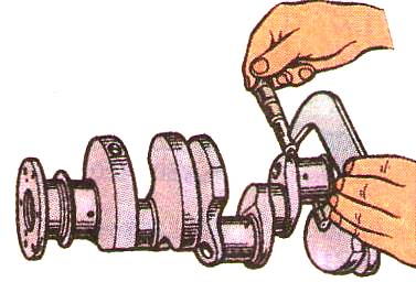
Determining the runout of the crankshaft journals and measuring their diameter is shown in fig. 2 and 3.
The piston is made of aluminum alloy.
The combustion chamber is located at the bottom of the piston.
In the upper part, the piston has four grooves (Since 1999, pistons with three grooves for rings, that is, with two compression rings, can be installed on a diesel engine) - compression rings are installed in the first three, and an oil scraper ring in the fourth.
The piston for the trapezoidal upper compression ring has an insert made of special cast iron. Holes for the piston pin are bored in the piston bosses.
Pistons are sorted into three size groups according to the outer diameter of the skirt (B, C, M). The group marking is applied to the piston crown. When installing on a diesel engine, the sleeves and pistons must be of the same size group.
Piston rings are made of cast iron. The upper compression ring is made of high-strength cast iron, chrome-plated, has the shape of an isosceles trapezoid in cross section and is installed in the groove on either side.
The second and third compression rings are tapered, on the end surface near the lock they are marked top.
Box type oil scraper with helical steel expander.
The piston pin is hollow, made of nickel-chromium steel.
The axial movement of the pin in the piston bosses is limited by the circlips.
Connecting rod - steel, I-section. A bushing is pressed into its upper head. There are holes in the upper head of the connecting rod and the bushing to lubricate the piston pin.
The boring of the bed in the lower head of the connecting rod for liners is assembled with a cover. Therefore, the replacement of connecting rod caps is not allowed.
The connecting rod and cap have the same numbers printed on their surfaces. In addition, the connecting rods have weight groups according to the mass of the upper and lower heads.
The designation of the mass group is applied on the end surface of the upper head of the connecting rod. On a diesel engine, connecting rods of the same group must be installed.
Crankshaft main and connecting rod bearing shells - steel-aluminum.
On diesel engines, two sizes of main and connecting rod bearing shells are used in accordance with the rating of the crankshaft journals.
Four repair sizes of liners are also provided for diesel repair.
The flywheel is made of cast iron, bolted to the crankshaft flange. A steel ring gear is pressed onto the flywheel.
Pistons of one set on a diesel engine must be of the same size group, corresponding to the size group of cylinder liners.
The difference in the mass of pistons of one set should not exceed 10 g.
The difference between the masses of connecting rods assembled with pistons should not exceed 30 g.
The out-of-roundness and tolerance of the profile of the longitudinal section of the hole in the bushing of the upper head of the connecting rod is 0.005 mm. When pressing
the sleeve must be provided with its symmetrical location relative to the middle plane of the connecting rod.
After boring, the surface of the hole of the upper head bushing should not have scratches and scratches, the roughness of the machined surface should be Ra≤0.63 µm.
On the upper surface of the sleeve, one spiral or radial risk with a width of not more than 0.1 mm is allowed.
Cracks and marks are not allowed on the surface of the connecting rod bolt. The bolt thread shouldbe clean, free of nicks and burrs.
The surface of the piston pin should be free of scratches, nicks and cracks.
The difference in the mass of fingers installed on one diesel engine should not exceed 10 g.
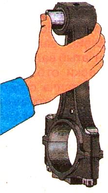
A finger that has not been lubricated with oil should easily turn in the connecting rod with the force of the hand, not have lateral swing and not fall out of the connecting rod under the influence of its own weight (Fig. 4).
Conrod bearing shells must be selected in accordance with the dimensions of the crankshaft journals.
The liners should sit in the beds of the connecting rods and caps with an interference fit of 0.22 to 0.08 mm.
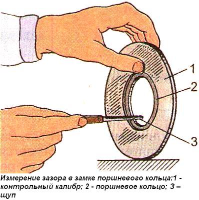
The radial clearance (clearance) between the piston ring and the control gauge 70-8618-3515 (Fig. 5) for the upper compression ring should not exceed 0.02 mm on no more than 10% of the surface and no closer than 20 ° from the lock; and for oil scraper rings - ovality should be within 0.15 ... 0.65 mm.
The gap at the junction of the rings should be in the range of 0.3 ... 0.6 mm, and adjustment of this gap is not allowed.
The tensile strength of the rings when bending the ring is not less than 441 Nm.
Crankshaft. Shaft straightening during machining and after HDTV hardening is not allowed.
Editing is allowed only after the fillet has been knurled. The deflection of the shaft during straightening should be no more than 1 mm.
When grinding crankpins, it is necessary to maintain the original radii of the crank (62.5 ± 0.04 mm) and fillets (4 + 0.3 mm).
The roughness of the machined surfaces of the connecting rod and main journals must correspond to Ra≤0.32 µm.
The out-of-roundness and tolerance of the profile of the longitudinal section of the connecting rod and main journals is 0.01 mm.
The hardness of the neck surfaces after grinding must be at least 46 HRCe. Hardening of fillets is not allowed.
After grinding to a repair size, the runout of the middle main journal relative to the extreme ones should not exceed 0.07 mm (for a new shaft - 0.03 mm).
The deviation from the parallelism of the forming surfaces of the connecting rod journals relative to the axis of the shaft mounted on the extreme main journals should not exceed 0.03 mm over a length of 100 mm.
The displacement of all connecting rod journals relative to the diametral plane of the 3rd main and 3rd crank journals (collapse of the journals) after regrinding should not exceed 0.3 mm.
The runout of the cylindrical and end surfaces of the flywheel mounting flange at the extreme points relative to the surfaces of the extreme main journals is allowed up to 0.05 mm (for a new shaft - no more than 0.03 mm).
The tubes must be tightly pressed into the connecting rod journals of the crankshaft; tube play is not allowed. The edges of the flared tubes should sink 1.3 mm relative to the surface of the necks.
The plugs must be recessed into the thread by at least 2 mm and be locked.
The crankshaft gear must be pressed with the mark outwards until it stops against the end of the main shaft journal.
The crankshaft must be dynamically balanced by removing metal from the periphery of any cheeks. Residual unbalance - no more than 900 g-mm at each end of the shaft.
The crankshaft assembly with counterweights must be dynamically balanced.
The mass should be adjusted by drilling, in counterweights in the radial direction of holes with a diameter of 10 mm to a depth of not more than 25 mm.
Residual unbalance - no more than 650 g/mm at each end of the shaft.
Crankshafts after final processing must be checked using a magnetic flaw detector for the absence of surface defects. After checking, the shafts must be demagnetized.
Flywheel assembly. Cracks and chipping of the working surface of the teeth of the flywheel crown are not allowed.
Reducing the length of the teeth of the crown (without the length of the chamfer) is allowed up to 16 mm (the length of the teeth of the new crown is 18 mm).
Wear of the teeth of the flywheel crown is allowed up to a thickness of 3.2 mm, with a caliper installation height of 2.4 mm (the tooth thickness of the new crown corresponds to 4.73 mm).
The flywheel ring must be heated to a temperature of 195...200°C before pressing on. The seats of the flywheel and the crown should not have nicks and burrs.
A gap in the mating between the end surface of the crown and the flywheel is not more than 0.5 mm. In one place on the arc, not more than 60 °.
The flywheel with crown must be dynamically balanced as an assembly with a pre-balanced crankshaft by drilling radial holes.
Residual unbalance at each end of the shaft - no more than 350 g / mm. After balancing, depersonalization of parts is not allowed.
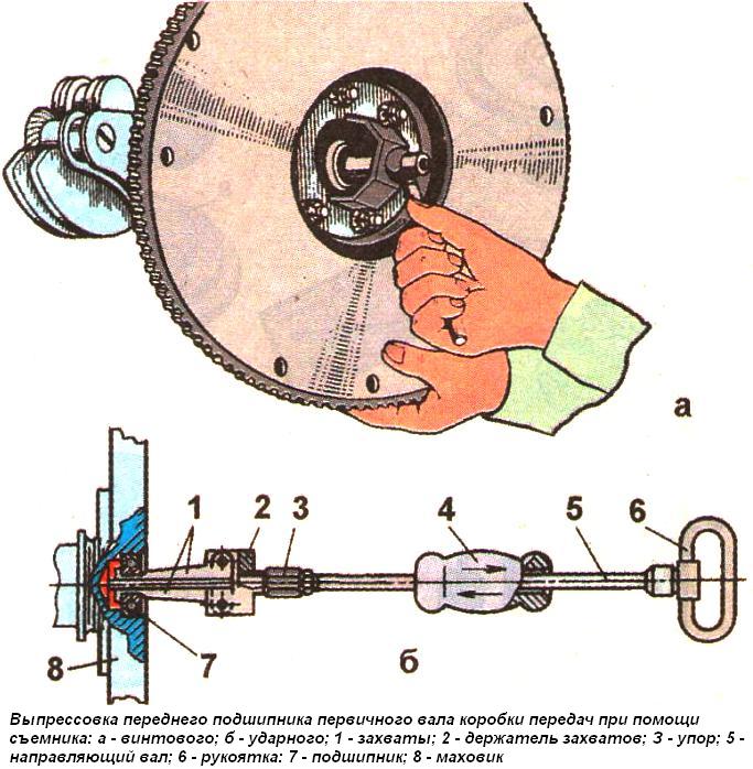
If it is necessary to replace the front bearing of the transmission input shaft, then before removing the flywheel from the shaft, it should bepress out with a screw extractor mod. And 803.16.000 (Fig. 6, a) or, having removed the flywheel, press out the bearing using an impact puller mod. 2476 (Fig. 6b).
Having installed the grippers on the ends of the bearing rings, they are pushed apart by a threaded stop 3, and then, when the load hits the stop of the shaft 5, the bearing is pressed out.
The surface of the flywheel mating with the surface of the clutch disc is ground. The surface roughness must be at least Ra≤1.0.

")
")
")
")
")