The clutch of the ZIL-131 car is single-disk, dry, installed in a cast iron housing 8
The clutch housing 9 is secured to the flywheel 2 of the crankshaft 1 with eight centering (special) bolts 23
The clutch pressure is created by sixteen springs 7 installed between the clutch housing 9 and the pressure plate 3.
Heat-insulating rings 10 are placed under the springs on the pressure plate side.
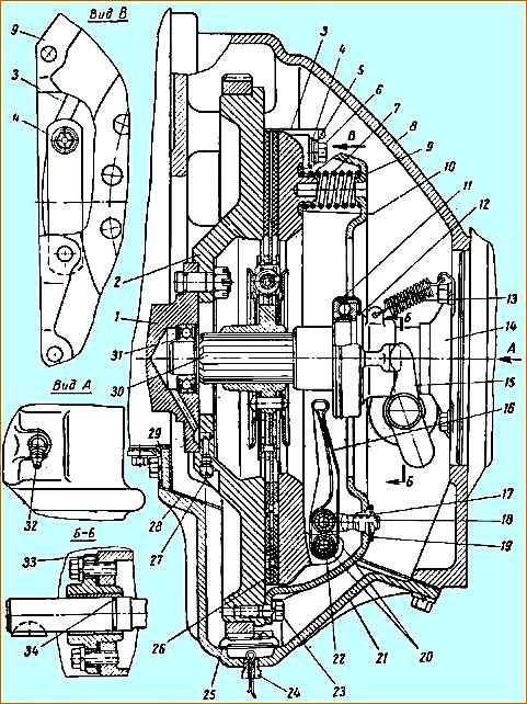
Clutch: 1 - crankshaft; 2 - flywheel; 3-pressure disk; 4 - spring plate; 5 - spring plate bushing; 6 - plate fastening bolt; 7 - pressure spring; 8 - clutch housing; 9 - cordon casing; 10 - heat-insulating washer of the pressure spring; 11 - clutch release bearing; 12 - bearing coupling; 13 - clutch release spring; 14 coupling guide; 15 - clutch release fork; 16 - clutch release lever; 17 - fork adjusting nut; 1c - Fork; 19 - support plastic of the adjusting nut; 20 - fingers; 21 - clutch housing cover; 22 - needle rollers; 23 - bolt securing the clutch housing to the flywheel; 24 - plug with cotter pin; 25 - oil collector shield; 26 - clutch driven disc; 27 - plug; 28 - gasket; 29 - shield; 30 - gearbox input shaft; 31 - front bearing of the gearbox input shaft; 32 - oiler
The transmission of torque from the clutch housing 9 to the driven disk is carried out through the pressure disk 3 by four pairs of spring plates 4.
The plates create a rigid connection between the pressure plate and the clutch housing in the circumferential and radial directions, while at the same time allowing the pressure plate to move relative to the clutch housing in the axial direction due to its flexibility, which is necessary for disengaging and engaging the clutch.
The plates are attached on one side to the casing, and on the other side, using special bushings 5 and bolts 6, to the pressure plate.
The switching device consists of four levers 16, which are connected with fingers 20 to the pressure plate and fork 18.
Needle rollers 22 are placed between the fingers 20 and the lever 16. The support points for the levers on the casing are the adjusting nuts 17, screwed onto the threaded ends of the forks.
The nuts are pressed to the clutch casing by elastic plates 19, each of which is secured to the casing with two bolts.
The elasticity of the plates 19 and the spherical supporting surface of the nuts in contact with the casing allow the forks 18 to make small rocking movements when disengaging and engaging the clutch.
The position of the clutch release levers 16 is adjusted with nuts 17, which are unscrewed after adjustment. These levers do not adjust during vehicle operation.
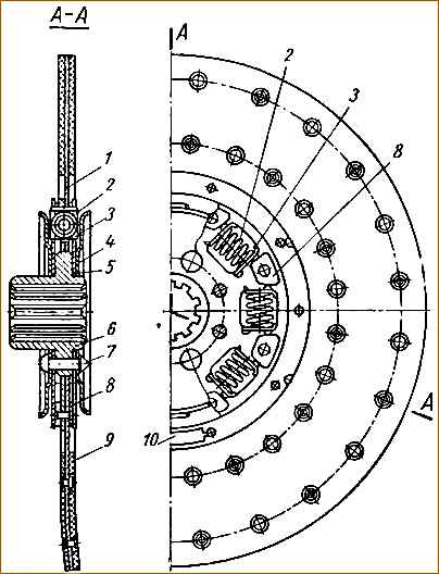
The driven clutch disc is made of steel, with friction linings, and has a torsional vibration damper (damper) of the friction type (with dry friction of steel on steel).
The elastic damper coupling consists of eight springs 2 evenly spaced around the circumference (Fig. 2).
Each spring, together with two support plates 3, is placed in holes punched in the driven disk 1 and the damper disks 5.
Support plate 3 has four lateral projections that hold it in the holes of the driven disk, and a hole with a flange on which the spring is centered.
The hub 6 of the driven disk, together with the damper disks riveted to it on both sides and the oil deflectors 4, can be rotated relative to the driven disk in both directions at a certain angle; in this case the springs are compressed.
The maximum angle of twist is determined by the full compression of the springs until the coils touch. Driven disk 1 is centered along the outer diameter of the hub flange 6.
The driven disk is balanced. Balancing is carried out by installing balancing plates on the driven disk 10 permissible imbalance 25 gcm.
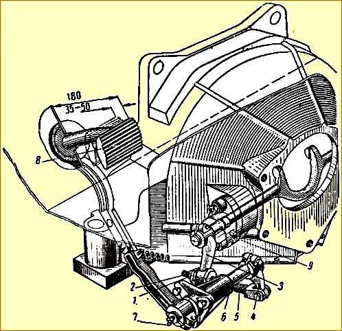
To disengage the clutch, use a pedal mounted on a bracket mounted on the left side member of the car frame.
The lower end of the pedal is connected by an adjustable rod 5 (Fig. 3) to lever 3 of the clutch release fork.
Pedal travel is limited by the stop on the cabin floor. The clutch release fork 15 (see Fig. 1) moves the clutch 12, on which the bearing 11 is mounted.
The bearing, pressing on the ends of the levers 16, disengages the clutch.
Clutch release bearing 11 has a constant supply of lubricant supplied at the bearing manufacturer, and is not lubricated during operation and repair.
If necessary, replace this bearing Looks new.
At the bottom of the clutch housing cover 21 there is an oil collector flap 25 and a plug 24 with a cotter pin for draining the oil entering the clutch housing from the gearbox.
The clutch is adapted for the vehicle to overcome deep fords.
To seal the clutch before fording, plug 24 must be replaced with a blind plug, which during normal operation is screwed into the bearing cover of the drive spur gear of the front axle gearbox.
Between the clutch housing 8 and the clutch housing cover 21, a sealing gasket 28 is installed; the sealing gasket is also installed under the flange of the clutch release fork 15; both gaskets are installed on sealing paste.
The same paste is used to seal the front and rear ends of the clutch housing when assembling the power unit.
To seal the clutch release fork 15, rubber rings 34 are installed on its necks on both sides.
At the lower part of the front end of the clutch housing there is a special rubberized shield 29 that closes the opening in the clutch housing.
The shield is attached to the clutch housing with two bolts and is pressed in the lower plane of the cylinder block by a protrusion on the front of the clutch housing cover.
When assembling, you must first tighten the shield mounting bolts until the bolt head touches the spring washer, without completely tightening them, then tighten the clutch housing cover 21 bolts, and only after that finally tighten the shield mounting bolts.
Adjusting the clutch drive
A correctly adjusted clutch should not slip in the engaged position, and when you press the pedal it should disengage completely (should not “drive”).
The pedal stroke should be 130-150 mm, the free stroke should be 35-50 mm, and the full stroke should be at least 180 mm
As the friction linings wear, the free play of the clutch pedal decreases, as a result of which the clutch may slip.
This leads to rapid wear of the driven disc and clutch release bearing.
In case of excessive free play (over 35-50 mm), when pressing the pedal all the way, the clutch does not disengage completely.
This leads to rapid wear of the driven disk and makes gear shifting difficult.
Pedal free play must be adjusted in the following order:
- 1. Unscrew locknut 2 (Fig. 3).
- 2. Adjust the free play of the clutch pedal by rotating the spherical adjusting nut 1; To reduce the free play of the pedal, the spherical nut should be screwed onto rod 5, and to increase the free play, unscrew it from the rod.
- 3. Tighten the locknut.
- 4. After adjustment, start the engine and check that the clutch is operating correctly.
When the clutch drive is correctly adjusted, the gap between the ends of the levers 16 (see Fig. 1) and the clutch release bearing should be 3-4 mm.
Clutch care
Maintenance consists of periodically adjusting the clutch drive, removing dirt, timely tightening all bolted connections, lubricating the clutch release fork and the clutch pedal shaft in accordance with the lubrication chart.
The front bearing 31 of the gearbox input shaft has a constant supply of lubricant supplied at the bearing manufacturer and is not lubricated during operation.
During repair work, this bearing is replaced with a new one, if necessary.
It is necessary to carefully monitor the tightening of the bolts securing the crankcase to the cylinder block.
The tightening torque of the bolts should be 8-10 kgm. The bolt must be tightened evenly, sequentially, crosswise.

")
")
")
")
")