The engine lubrication system is designed to supply cooled and purified oil to the rubbing surfaces of the engine, remove heat and wear products from them
The engine lubrication system diagram is shown in Fig. 1.
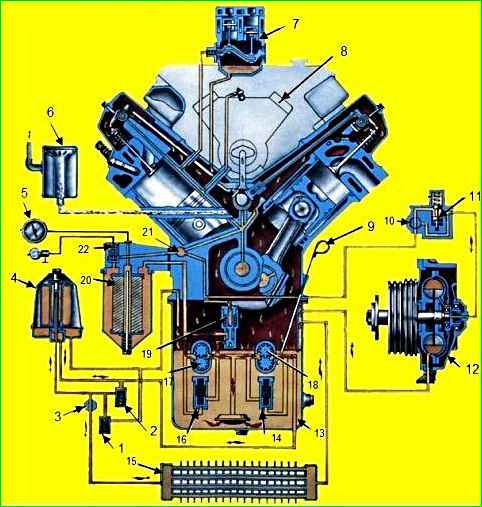
Oil filter 20 is attached with three bolts to the right wall of the cylinder block.
Centrifugal filter 4 for oil purification is installed on the front cover of the cylinder block on the right side of the engine.
The oil pump is located in the front part of the oil sump cavity and is attached with three bolts to the engine block; the dismantling of these units was described above.
When disassembling the oil pump unscrew the bolts and remove the suction and supply pipes.
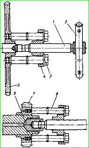
Use puller I-80102.000 (Fig. 2), compress gear 1 (Fig. 3).
When installing, screw the puller bolts into the threaded holes “A” of gear 1. Remove 31 keys 2 from the shaft.
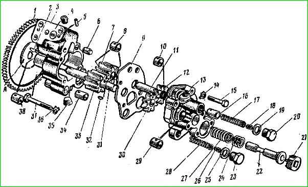
Unscrew plugs 20, 21 and 23, remove sealing gaskets 19 and 25. Remove adjusting washers 18 and 26 from plugs 20 and 23.
From bodies 3 and 13, remove valve springs 17 and 28, valves 16 and 34, lubrication system valve 22, adjusting washers 24 and spring 27.
Unlock and unscrew two bolts 15 from the side of the body 13 and two bolts 37 from the side of the body 3, remove the lock washers 14 and 36.
Separate housing 13 from spacer 9 and remove it complete with gear 12 and axle 11.
Remove gear 12 from housing 13.
Remove gear 30, key 32 and spacer 9 from shaft 31.
Remove from housing 3 roller 31 assembled with gear 33, gear 7 assembled with bushings 8.
If necessary, press axis 11 out of housing 13, and roller 31 out of gear 33 and remove the key.
Do not press out the installation sleeves 6 and pins 5 unless necessary. To clean the oil channels in housings 3 and 13, use a wrench (with 5 and 8 mm hexagons) to unscrew plugs 4, 35, etc.
In case of wear or damage, press bushings 29, 38 and 8, 10 out of the housings and gears.
Assemble the oil pump in the reverse order of disassembly. In this case, it is necessary to fulfill a number of requirements.
Do not reuse lock washers 14 and 36 during assembly.
In the assembled pump, the rotation of roller 1 behind gear 1 should be free, without jamming.
Repair and replacement of worn parts must be carried out at the interfaces of the main parts.
When pressing axle 11 into housing 13, ensure that the axle protrudes from the plane of the housing connector by 47 ± 0.2 mm.
After assembly, check the oil pump supply on a stand using a motor of oil M10G2k at a temperature of 80-85 °C.
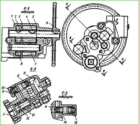
When checking, adjust valves 9, 13 and 14 (Fig. 4).
When checking the pump, the drive shaft should rotate at a frequency of 2750-2800 rpm.
The vacuum in the suction tract of the pump should be 90 -110 mm Hg. st.
When tested under these conditions, the feed should be:
- - at the discharge section (at an outlet pressure of 3.5-4.0 kgf/cm 2) no less than 82 l/min;
- - at the radiator section (at an outlet pressure of 7.0-7.5 kgf/cm 2) no less than 27 l/min.
- - adjust the pressure at the start of opening of valves 9, 13 and 14, respectively, with packs of adjusting washers 11, 12 and 15.
The opening of valve 13 of the lubrication system should begin at an oil pressure in channel F of 4.0—4.5 kgf/cm 2.
The opening of the safety valves of the discharge section (channel D) and radiator section (channel N) should be at an oil pressure of 8.5-9.5 kgf/cm 2
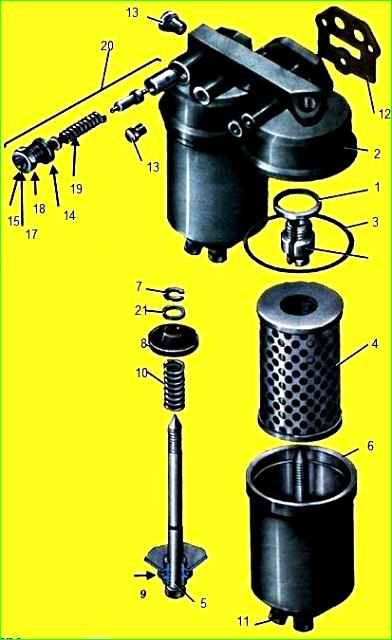
To disassemble the oil purification filter (Fig. 5), unscrew the rods 5 and remove 2 caps 6 from the body.
O-ring 3 should only be removed when replacing.
Unscrew the plug 13, remove the sealing gasket 12 and adjusting washers 14, remove the spring 16, the alarm housing 18 assembled with the moving contact 17 and the bypass valve 20 from the housing hole.
Remove ring 7, sealing cup 8, spring 10 from rod 5, remove rod from cap, remove sealing gasket from it. To clean the oil channels, remove the plugs.
Assemble the oil filter in the reverse order of disassembly.
After assembly, to assess the technical condition of sealing rings 3 and 9, check the tightness of the filter with an air pressure of 5 kgf/cm 2 by lowering it into water with a temperature of 60˚C. Supply air pressure through the inlet.
If the rings are leaking, replace them with new ones.
Check and, if necessary, adjust with washers 14 the pressure at which the bypass valve 20 begins to open and the pressure at which the filter clogging indicator turns on (when the indicator light comes on).
The moment of valve opening is determined by the beginning of a stream of oil flowing out of the hole behind the valve.
The adjustment is considered correct (using no more than three adjusting washers) if the pressure in cavity “N” at the beginning of the valve opening is 2.5-3 kgf/cm 2.
If the opening pressure of the bypass valve does not correspond to the required value, replace the valve spring.
Check the operation of the light indicator sensor for filter element clogging in an electrical circuit with a voltage of 12-24 V.
Closing the circuit between the moving 17 and fixed 15 contacts (the light comes on) must occur at an excess pressure in cavity “N” equal to or less than the pressure at which the bypass valve begins to open, but not lower than 2 kgf/cm 2
The centrifugal oil purification filter is more convenient to disassemble when installing it vertically on a stand or in a vice.
To disassemble, unscrew the four bolts (being careful not to damage the gasket), separate the filter from the front cover of the cylinder block and install it on a stand or secure it in a vice.
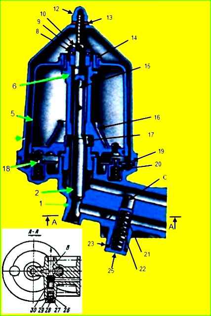
When disassembling, unscrew nut 12 (Fig. 6), gasket 13 and filter cap 7.
Rotate the rotor cap 5 so that the pins 18 of the stopper enter the holes on the bottom of the rotor 6.
Unscrew nut 11 and remove the rotor cap 5 together with nut 11.
Unscrew nut 10, remove washer 9, bearing 8, rotor 6 assembly, stopper plate 19, pin 18 and spring 20.
If necessary, unscrew axle 15 and remove tube 2. Unscrew plugs 25 and 27, remove sealing gaskets 28, 26, adjusting washers 24 and 28, remove springs 22 and 29, valves 21 and 30.
Assemble the filter in the reverse order of disassembly. Tighten axle 15 (tightening torque 30-35 kgf/m).
Install bearing 8 so that the ring with the increased inner diameter is at the bottom.
Align the marks on the cap 5 and rotor 6 with an accuracy of 5 mm (otherwise the balancing of the rotor with the cap assembly will be disrupted).
After assembly, check and, if necessary, adjust the valve opening pressure using washers 24 and 28.
Bypass plunger 21 should open at a pressure in the channel of 6.0 - 6.6 kgf/cm 2.
Drain valve 30 should open at a pressure in channel “B” of 1.1-1.2 kgf/cm 2.
Oil radiator rinse first in a hot 10% caustic soda solution, then in hot water.
The degreasing solution and water during washing should circulate in directions opposite to the flow of oil and air.
After flushing, check the radiator for leaks with air under a pressure of no more than 4 kgf/cm 2 (with immersion in water). In the event of a leak, repair the radiator and solder the leakage areas with soft solder.
Fix frame cracks by gas welding, followed by cleaning the weld seam and painting.

")
")
")
")
")