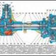
Carburetor K-126 is installed on engines GAZ-21, GAZ-24, GAZ-53, GAZ-66, etc.
Very simple and reliable carburetor
A feature of the K-126B carburetor is that all jets can be washed and blown without disassembling the carburetor
The carburetor has two mixing chambers: primary and secondary. The primary chamber operates in all engine modes.
The secondary chamber comes into operation under heavy load (approximately after 2/3 throttle stroke of the primary chamber).
To ensure uninterrupted engine operation in all modes, the carburetor has the following metering devices: a cold running system of the primary chamber, a transition system of the secondary chamber, main metering systems of the primary and secondary chambers, an economizer system, a cold engine starting system and an accelerator pump system.
All elements of the dosing systems are located in the body of the float chamber, its cover and the housing of the mixing chambers.
The body and cover of the float chamber are cast from zinc alloy.
The housing of the mixing chambers is cast from aluminum alloy.
Between the body of the float chamber, its cover and the body of the mixing chambers, sealing cardboard gaskets are installed.
In the body of the float chamber there are: two large 6 and two small diffusers 7, two main fuel jets 28, two air brake jets 21 of the main metering systems, two emulsion tubes and, located in wells, fuel 13 and air jets of the idle system , economizer and guide bushing 27, accelerator pump 24 with discharge and check valves.
The nozzles of the main dosing systems are located in small diffusers of the primary and secondary chambers.
The diffusers are pressed into the float chamber body; the float chamber body has a window 15 for monitoring the fuel level and the operation of the float mechanism.
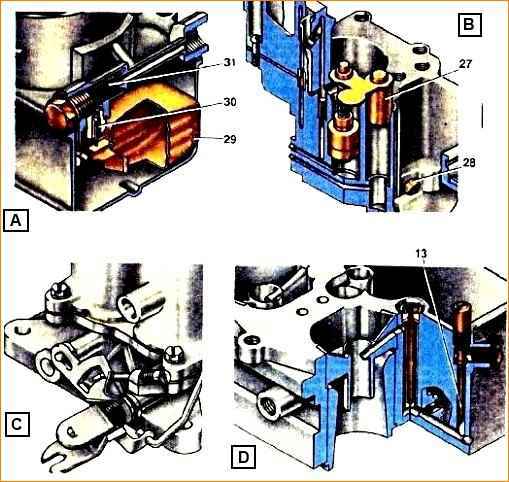
All jet channels are equipped with plugs to provide access to them without disassembling the carburetor.
The idle fuel jet may be turned outside, for which purpose its body is brought out through the cover upwards.
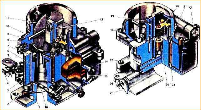
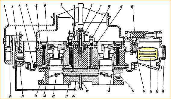
Carburetor K-126: 1 - Mixing chamber; 2 - Mixture quality screw; 3 - Vacuum regulator hole; 4 - Throttle valve drive lever; 5 - Mixture amount screw; 6 - Large diffuser; 7 - Small diffuser; 8 - Air damper axis; 9 - Air damper spring; 10 - Float chamber cover; 11. Air damper; 12 - Acceleration pump nozzle. 13. Idle fuel jet; 14 - Float chamber housing; 15 - Viewing window; 16 - Throttle valve; 17 - Housing fastening screw; 18 - Screw securing the cover; 19 - Economizer sprayer; 20 - Accelerator pump drive. 21 - Main air jet; 22 - Filter plug; 23. Emulsion tube; 24 - Acceleration pump piston; 25 - Drive link; 26 - Secondary throttle valve axis; 27 - Guide sleeve; 28 - Main fuel jet; 29 - Float; 30 - Fuel valve; 31 - Fuel filter
In the float chamber cover there is an air damper 11 with a semi-automatic drive.
The air damper drive is connected to the throttle axis of the primary chamber by a system of levers and rods, which, when starting a sluggish engine, open the throttle valve to the angle necessary to maintain the engine starting speed.
The secondary throttle valve is tightly closed.
This system consists of an air damper drive lever, which with one shoulder acts on the air damper axis lever, and with the other, through a rod, on the idle throttle lever, which, turning, presses on the primary chamber damper and opens it.
A float mechanism is attached to the carburetor cover, which consists of a float suspended on an axis and a fuel supply valve 30.
The carburetor float is made of 0.2 mm thick sheet brass.
The fuel supply valve is dismountable and consists of a body and a shut-off needle.
Valve seat diameter 2.2 mm. The needle cone has a special sealing washer made of a fluorine rubber compound.
Fuel entering the float chamber passes through strainer 31.
In the housing of the mixing chambers there are two throttle valves 16 of the primary chamber and the secondary chamber, adjusting screw 2 of the cooling system high speed, toxicity screw, channels of the idle system, which serve to ensure coordinated operation of the idle system and the main metering system of the primary chamber, hole 3 for supplying vacuum to the vacuum ignition timing regulator, as well as the transition system of the secondary chamber.
The carburetor idle system consists of a fuel jet 13, an air jet and two holes in the primary mixing chamber (upper and lower).
The lower hole is equipped with a screw 2 to regulate the composition of the combustible mixture.
The idle fuel jet is located below the fuel level and is switched on after the main jet of the primary chamber.
The fuel is emulsified by an air jet.
The required system performance is achieved by the idle fuel jet, the air brake jet, and the size and location of the vias in the primary mixing chamber.
The main metering system of each chamber consists of large and small diffusers, emulsified tubes, main fuel and main air jets.
Main air jet 21 regulates the flow of air inside the emulsion tube 23 located in the emulsion well.
The emulsion tube has special holes designed to obtain the necessary characteristics of the system.
The idle system and the main metering system of the primary chamber provide the necessary fuel consumption in all main engine operating modes.
The economizer system consists of a guide bushing 27, a valve 23 and a spray nozzle 19.
The economizer system is activated until the secondary chamber throttle valve is fully open.
It should be noted that at full load, in addition to the economizer system, the main metering systems of both chambers operate and very little fuel continues to flow through the idle system.
The accelerator pump system consists of a piston 24, a drive mechanism 20 for the intake and discharge (exhaust) valves, and a spray nozzle 12 discharged into the air pipe of the primary chamber.
The system is driven by the throttle axis of the primary chamber and operates when the vehicle accelerates.
The drive lever 4 is rigidly mounted on the axis of the throttle valve of the primary chamber. Also rigidly fixed to the axle is the linkage of the drawstring 25.
The slide is freely mounted on the axis of the damper 16 and has two grooves.
In the first of them the driver moves, and in the second - the pin with the roller of the lever 26 of the drive of the axis 8 of the secondary damper mounted on it.
The flaps are held in the closed position by springs mounted on the axis of the primary chamber and the axis of the secondary chamber.
The slide 25 also constantly strives to close the shutter of the secondary chamber, since it is acted upon by a return spring attached to the axis of the primary chamber.
When the lever 4 of the drive of the primary chamber axis moves, the leash of the primary chamber lever first moves freely in the groove of the slide 25 (thus, only the primary chamber flap opens), and after approximately 2/3 of its stroke, the leash begins to turn it.
Switch 25 of the secondary damper drive opens the secondary throttle valve. When the gas is released, the springs return the entire system of levers to their original position.
The carburetor must be washed in clean unleaded gasoline or acetone, followed by blowing with compressed air.
Condition of the main parts and assemblies arriving for assembly
All channels of the body parts must be thoroughly washed and blown with compressed air.
It is allowed to repair broken fastening flanges that do not involve internal cavities and channels by welding.
The surfaces of the connecting flanges of the housing parts must be flat without nicks or irregularities.
When checking on a slab, the out-of-flatness should not exceed 0.1 mm.
Performance of jets d installation in the carburetor should be checked on a device model NIIAT-528 or another device that allows you to check the performance of the jets:
- - main air jet Ø 0.8+0.06mm;
- - idle fuel jet Ø 0.75+0.06mm;
- - idle air jet Ø 1.5+0.06mm;
- - economizer spray Ø 0.7+0.06mm;
- - accelerator pump nozzle Ø 0.6+0.05mm.
The performance value of the K-126B carburetor jets should be within the following limits:
- - main fuel jet - 340 ± 4.5 cm 3 /min;
- - diaphragm mechanism jet - 75 ± 3 cm 3/min;
- - vacuum jet of the diaphragm mechanism - 310 ± 7 cm 3/min.
Size of emulsion holes in the mixing chamber:
- - upper Ø 1.0+0.06 ;
- - lower Ø 1.3+0.06mm.
The thread of the jets should not have nicks.
The economizer valve must be sealed. The tightness must be checked with water under a pressure of 1200 mm water. Art. Water flow under the valve is allowed no more than 4 drops per minute.
The valve stem should protrude from the body within 1.1+0.3 mm.
The diffuser body must be intact, without breaks or cracks.
The float must not have holes or dents. It must be tested for leaks by immersion in hot water. The appearance of air bubbles in a working float is not allowed.
The weight of the float should be within 13.3 ± 0.7 g.
The fuel supply valve must be tested for leaks with a vacuum of 100 mmHg. Art., through water; in this case, leakage of no more than 10 drops per minute is allowed.
Disassembling the carburetor
The carburetor is disassembled to clean the float chamber, change jets and mating parts if their fits are not correct.
Disassemble the carburetor in the following order:
- - unpin and remove one end of the low-speed rod from the hole in the lever;
- - unscrew the seven screws securing the float chamber cover, remove the cover, being careful not to damage the cardboard gasket underneath;
- - remove the float axis and remove the float. Remove the fuel valve needle along with the spring;
Unscrew the fuel valve body together with the paronite gasket. It is not recommended to remove the air damper unless necessary.
To remove the damper, unscrew the two screws securing it, then unscrew the screw securing the drive lever bushing, remove the lever together with the bushing and spring. Remove the air damper axle assembly with the lever and return spring.
- - unscrew the filter plug, release the paronite gasket and remove the mesh filter;
- - then proceed to disassemble the float chamber. Remove the cotter pin from the accelerator pump drive shackle.
Carefully holding the accelerator pump drive with your hand from above, release the drive rod from the lever mounted on the throttle axis, and remove the shackle.
Remove the accelerator pump drive rod assembly with the piston and economizer drive from the carburetor body.
It is not recommended to disassemble the accelerator pump drive. If it is necessary to replace the accelerator pump piston or for other reasons, unscrew the installation nuts of the accelerator pump and economizer rods and remove the rods by removing the springs;
- - unscrew the plugs on the outside of the housing, unscrew the main fuel jets of the primary and secondary chambers and the idle air jet;
- - to access the emulsion tubes, unscrew the main air jets of the primary and secondary chambers.
- - unscrew the idle fuel jet and the economizer valve. Remove the accelerator pump discharge valve;
- - unscrew the large nut at the front of the housing and carefully, so as not to damage the gasket, remove the sight glass of the float chamber;
- - small diffusers are not allowed to be pressed out of the carburetor body;
- - unscrew the four fastening screws and disconnect the mixing chamber from the float chamber. Remove the two large diffusers and the gasket between the chambers.
- - The mixing chamber should not be disassembled unless necessary. If the throttle axis swings in the bosses or the seal of the dampers to the chamber walls is unsatisfactory, and the axial play of the damper when open exceeds 0.3 mm, then the mixing chamber should be disassembled.
- - to completely disassemble the mixing chamber you should:
- - unscrew the nut of the throttle axis lever of the primary chamber and two screws securing the drive mechanism cover;
- - remove the drive lever and low-speed lever with mounting washers, and the mechanism cover;
- - remove the link with the spring from the throttle axis of the primary chamber.
Unscrew two screws each and remove the chokes of the primary and secondary chambers;
- - remove the accelerator pump drive lever from the throttle axis of the primary chamber and the nut and washer from the secondary chamber axis;
- - remove both axes to the body and, at the same time removing the return spring of the primary chamber axis.
Carburetor assembly
The float should swing freely on its axis without jamming, while ensuring a needle stroke of at least 1.5 mm.
The fuel level in the carburetor float chamber should be 18.5-21.5 mm below the upper plane of the body and correspond to the marks on the carburetor body, which are visible through the inspection windows.
To obtain the correct level in the float chamber, it is allowed to bend the float bracket.
The diaphragm mechanism must be sealed. The check is carried out at a special stand.
At a vacuum of 1500-1700 mm water, art. no more than three air bubbles per second are allowed.
The diaphragm mechanism cover and the diaphragm drive linkage cover must be sealed.
The throttle axis must rotate freely in the bearings without jamming. The circumferential gaps between the dampers and the housings should not exceed:
- - for throttle valves—0.06 mm;
- - for air dampers - 0.2 mm.
When the air damper is completely closed, the damper throttles should open at least 12° from their full open position.
The economizer valve must be fully engaged with the throttles fully open.
Test
The assembled carburetor must be checked for leaks and the height of the fuel level in the float chamber using a device model NIIAT-355.
At an excess pressure of 0.3-0.32 kg/cm 2 for gasoline with a specific gravity of 0.720-0.750 g/cm 3 the fuel level in the float chamber should be 20 ± 1 mm to the plane of the carburetor connector.
The performance of the accelerator pump must be at least 10 cm 3 per 10 piston strokes.
Checking the full engagement of the economizer valve is carried out by measuring: the gap between the bar and the economizer drive nut, the distance between the upper plane of the carburetor cover and the upper plane of the bar.
The gap between the bar and the nut of the economizer drive rod when the top plane of the bar is positioned at a distance of 13 ± 0.2 mm from the top plane of the float chamber connector should be 3 ± 0.2 mm.
The distance between the upper split plane of the carburetor cover and the upper plane of the bar should be 21.5 ± 0.2 mm.
Checking the operation of the diaphragm mechanism of the centrifugal speed limiter is carried out on a special stand.
The carburetor speed limiter, when working with a reference sensor, should provide automatic limitation of the engine crankshaft speed when operating with an air filter within the limits:
- - according to speed characteristics - 3200-3400 rpm;
- - at idle speed - 3450-3550 rpm.
All carburetors coming out of repair must be tested on the engine in order to determine their basic operating qualities, ensuring:
- - ease of starting the engine;
- - stable engine operation at low idle speed;
- - no failures in work.
The minimum stable engine crankshaft speed when idling should be within 400-500 rpm.
When checking engine operation in various modes (with and without load), the carburetor must ensure a smooth transition without failures from one engine operating mode to another.
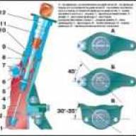
Carburetor adjustment
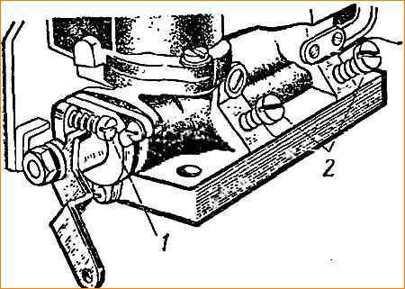
Idle speed adjustment is performed using a thrust screw 1 (Fig. 3), which limits the closing of the throttles, and two screws 2, 2, which change the composition of the working mixture, on a well-warmed-up engine and with a working ignition system.
Particular attention should be paid to the serviceability of the spark plugs and the correct gap in their electrodes.
When adjusting, it should be taken into account that the carburetor is a two-chamber carburetor and the composition of the working mixture in each chamber is regulated independently.
When starting the adjustment, you should tighten screws 2 all the way, and then unscrew them two turns each.
Start the engine and set screw 1 to the smallest throttle opening at which the engine operates quite stably.
Then lean the mixture with one of screws 2, tightening it ¼ turn at each test until the engine starts to work intermittently.
After this, enrich the mixture by turning out screw 2 by ½ turn. Perform the same operations with the second screw 2.
Having adjusted the composition of the mixture, try to reduce the idle speed by unscrewing the thrust screw 1 of the throttles, and then again lean the mixture with both screws alternately, as indicated above.
To check the idle speed adjustment, sharply press the throttle pedal and release it sharply.
If the engine stops, the speed must be increased using the throttle stop screw.
A properly adjusted engine should operate steadily at 475-525 rpm.

")
")
")
")
")