When disconnecting the high pressure fuel line from the injector (except for model 51 injectors), hold the injector fitting with a wrench to prevent it from unscrewing and fuel leakage
After disconnecting, check the tightness of the fitting without removing the injector from the engine
When servicing each injector, check and adjust in the following order:
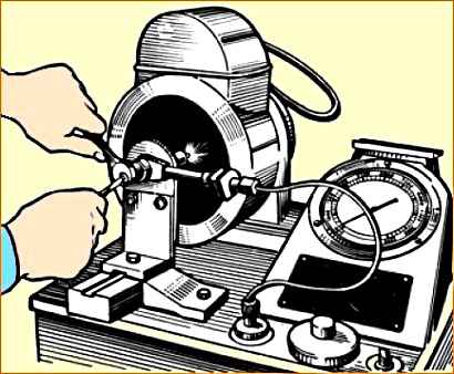
It is recommended to make adjustments on a special stand, type KI-3333, that meets GOST 10579-88.
The injection start pressure must be determined from the table
- The injection start pressure of injectors of models 267-02, 267-10, 261-10(11) is adjusted with a screw when the injector cap is removed and the lock nut is unscrewed. When screwing in a screw, the pressure increases, and when turning it out, it decreases.
- The injection start pressure of the nozzle of models 204-50, 204-50.01 and 51-01 is adjusted using adjusting washers. As their total thickness increases, the pressure increases, and as it decreases, it decreases.
2. Check that the sprayer is tight against the needle locking cone and that there are no leaks at the high pressure line seals.
To do this, create a fuel pressure in the nozzle 1-1.5 MPa (10-15 kgf/cm 2) below the injection start pressure.
In this case, there should be no leakage of fuel from the spray holes for 15 seconds; It is allowed to moisten the nozzle of the sprayer without the fuel coming off in the form of a drop.
Check the tightness of the high-pressure line seals by holding it under pressure for 2 minutes; There should not be a tearing drop of fuel formed at the upper end of the nozzle nut (when installing the nozzle at an angle of 15° to the horizontal surface).
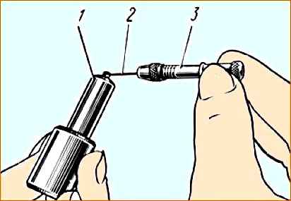
3. Check the mobility of the needle by pumping fuel through a nozzle adjusted to a given injection start pressure on a pressure testing stand, at an injection frequency of 30-40 per minute.
It is allowed to check the mobility of the needle simultaneously with checking the quality of spraying according to step 4.
4. Check the quality of atomization on a testing stand by pumping fuel through a nozzle adjusted to a given injection start pressure at a frequency of 60-80 injections per minute.
Atomization quality is considered satisfactory if the fuel is injected into the atmosphere in a mist-like state and is evenly distributed both over all jets and across the cross section of each jet.
The beginning and end of the injection must be clear. After injection is completed, the nozzle of the sprayer can be moistened without forming a drop.
Fuel injection from a new injector is accompanied by a characteristic sharp sound. The absence of a sharp sound from used injectors does not mean a decrease in the quality of their work.
5. Check the tightness of the seal, connection and outer surfaces of the low-pressure cavity by pressure testing with air at a pressure of 0.45±0.05 MPa (4.5±0.5 kgf/cm 2).
Passing air for 10 seconds is not allowed when air is supplied from the side of the sprayer spout.
6. Check the tightness of the “nozzle-nozzle nut” connections by pressure testing with air at a pressure of 0.5±0.1 MPa (51 kgf/cm 2) for 10 seconds with air supplied from the side of the nozzle nozzle.
Passing air bubbles through the threads of the sprayer nut when immersing it in diesel fuel is not allowed.
If one or more spray holes of the atomizer become coked or clogged, disassemble the nozzle, clean the nozzle parts and rinse thoroughly in filtered diesel fuel.
If the sealing cone is not sealed, the sprayer assembly must be replaced. Replacing parts in the atomizer is not allowed.
Adjust each injector to the injection start pressure:
Disassemble the nozzle in the following sequence:
Injectors models 267-02, 267-10, 204-50, 204-50.01, 261-10(11):
- 1. unscrew the injector cap;
- 2. unscrew the lock nut and turn out the adjusting screw until it stops;
- 3. unscrew the spring nut one and a half to two turns;
- 4. unscrew the sprayer nut;
- 5. remove the sprayer, protecting the sprayer needle from falling out.
Each injector must be adjusted to the injection start pressure
YAM3-236NE2,BE2 with common cylinder heads:
- Nozzle model 267.1112010-02 → injection start pressure - 26.5 +0.8 MPa (270 +8 MPa/cm 2);
- Nozzle model 204.1112010-50.01 → injection start pressure - 26.5 +1.2 MPa (270 +12 kgf/cm 2)
YAM3-236NE2,BE2 with common cylinder heads and V-shaped injection pump:
- Nozzle model 267.1112010-10 → pressure injection start time - 26.5 +0.8 MPa (270 +8 MPa/cm 2);
- Nozzle model 204.1112010-50 → injection start pressure - 26.5+1.2 MPa (270+12 kgf/cm 2)
YAM3-236NE2,BE2 with individual cylinder heads:
- Nozzle model 51.1112010-01 → injection start pressure - 26.5 +1.2 MPa (270 +12 kgf/cm 2)
YAM3-236N,B,NE,BE:
- Nozzle model 261.1112010-11 (10) → injection start pressure - 20.6 +0.8 MPa (210+8 kgf/cm 2)
Nozzle model 51-01:
- 1. unscrew the sprayer nut;
- 2. remove the sprayer, protecting the sprayer needle from falling out.
Remove carbon deposits from the sprayer body with a metal brush or sandpaper with a grain size no coarser than M40.
Clean the spray holes with steel wire with a diameter of 0.3 mm (for the nozzle nozzle of models 267-02, 267-10, 204-50, 204-50.01 and 261-10(11)) and a diameter of 0.28 mm (for the nozzle injectors model 51-01).
It is not allowed to use hard materials or sandpaper to clean the internal cavities of the sprayer body and needle surfaces.
Before assembling, thoroughly rinse the sprayer and needle in filtered diesel fuel.
The needle should move easily: extended from the sprayer body by one third of the length of the guide, when the sprayer is tilted at an angle of 45° from the vertical, the needle should smoothly, without delay, completely lower under the influence of its own weight.
Assemble the injector in the reverse order of disassembly.
When tightening the nut, turn the sprayer against the direction of screwing the nut until it stops against the fixing pins and, holding it in this position, screw the nut by hand, after which the nut is finally tightened.
The tightening torque of the sprayer nut is 70-80 Nm (7-8 kgcm), the nozzle fitting is 80-100 Nm (8-10 kgcm).
After assembly, adjust the nozzle to the injection start pressure and check the quality of fuel atomization and the accuracy of the nozzle.
The installation of injectors or nozzles that are not suitable for this engine is strictly prohibited.

")
")
")
")
")