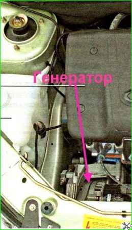
The generator is mounted on a bracket fixed to the engine
The generator is attached to the bracket with two bolts and nuts
The head of the upper bolt is kept from turning by two protrusions on the bracket
The nut of the lower bolt is installed in the hexagonal recess of the bracket.
A spacer sleeve is installed in the lower left hole of the bracket for the generator mounting bolt.
Removing and disassembling the generator
First of all, remove the negative terminal from the battery.
Remove the generator belt.
To remove the belt, read the article “Replacing the alternator belt.”

Press the lock of the generator excitation wire block and disconnect the block from the voltage regulator connector

Using a 13mm socket, unscrew the nut securing the wire lugs to terminal “B+” and remove from the terminal

We unscrew the 17 bolt that secures the generator from below and remove this bolt.
Remove the nut from the generator bracket.

Unscrew the nut of the bolt of the upper mounting of the generator using a 13 socket

Remove the generator for subsequent disassembly

Press the three latches of the casing and pry it off with a screwdriver

Remove the casing

Use a 8mm socket to unscrew the two bolts securing the voltage regulator

Use a 12 mm wrench to unscrew the nut securing the brush holder terminal to terminal “B+” of the generator

Use a screwdriver to pry up the brush holder block and disconnect it from the rectifier unit

Remove the regulator with brush holder

Unscrew the three bolts with a 8-head head that secure the rectifier block

Press the spring metal clamp using a screwdriver and remove the end of one of the stator windings. We also disconnect the remaining ends of the windings

Using a 12mm wrench, unscrew the nut securing the “B+” terminal

Remove the rectifier block

Installing a screwdriver between the stator housing and the rotor impeller and thus holding the rotor from turning, use a 24mm head to unscrew the nut securing the generator pulley.

Remove the pulley from the rotor shaft

Use a 8mm head to unscrew the four bolts holding the covers together.
Before disconnecting the generator covers, you need to mark the location.

Insert a screwdriver into the gap between the covers

Disconnect the generator covers. Mark the position of the stator relative to the cover

Disconnect the back cover and stator

Remove the bolt with a square head (terminal “B+”) with an insulating tube

Remove the plastic bushing from the rear bearing.

After screwing a nut onto the threaded end of the rotor shaft, use a hammer with a plastic tip to knock the rotor shaft out of the front cover

Use a two-jaw puller to press the rear bearing from the rotor shaft

We use a tester to check the stator and rotor windings for open circuits and short circuits to the housing
Assemble the generator in reverse order.
To install the rear bearing, we support the front end of the rotor shaft on a wooden block and press the bearing onto the rear end of the shaft with a suitable piece of pipe or head, applying force to the inner ring of the bearing.

")
")
")
")
")