Checking electrical circuits of automatic transmission
The following are general methods for checking the integrity of electrical circuits, checking for short circuits using an ohmmeter and a voltmeter
Checking the integrity of the electrical circuit
Loss of electrical circuit integrity can be caused by the following reasons:
- - disconnecting the harness block
- - weak connection of the harness block;
- - contamination, oxidation, corrosion of contacts;
- - deformation of contacts;
- - wire damage.
Check circuit integrity in the following sequence:
- 1. Disconnect the ground wire terminal from the battery.
- 2. Visually check that the harness connectors are connected on both sides of the electrical circuit and that the locking latches are latched.
- 3. Disconnect the pads, visually check the contacts for dirt, corrosion, and deformation.
- 4. By pulling the wires next to the block, make sure that the wire and the terminal are tightly pressed together and that the terminal is fixed inside the block.
- 5. Using a probe of a given diameter and length corresponding to the size of the contact in the mating block, make sure that the terminals of the harness blocks provide a reliable connection (the terminals are not recessed in the block, the probe fits tightly into the terminal).
- 6. Using an ohmmeter, measure the resistance of the circuit between the pads.
The resistance of a working circuit should be less than 1 ohm. To avoid damage to the terminals, it is allowed to use probes of a given diameter for measurements that correspond to the size of the contacts in the mating blocks.
Checking circuit short to ground
Perform the check in the following sequence:
- 1. Disconnect the connectors on both sides of the electrical circuit.
- 2. Connect the probe, one end connected to the + of the battery, to the terminal of the circuit being tested.
If the probe lights up, it means the circuit being tested is shorted to ground.
To avoid damage to the terminal, the probe must be connected using a probe of a given diameter corresponding to the size of the contact in the mating block.
Checking the circuit short to the on-board network
Perform the check in the following sequence:
- 1. Disconnect the connector on one side of the electrical circuit.
- 2. Connect the probe, one end connected to ground, to the terminal of the circuit being tested.
- If the probe lights up, it means that the circuit being tested is closed to the on-board network.
- 3. Attach the disconnected block.
- 4. Disconnect the connector on the other side of the electrical circuit.
Run check 2.
To avoid damage to the terminal, the probe must be connected using a probe of a given diameter corresponding to the size of the contact in the mating block.
Measuring voltage at wiring harness contacts
Perform the check in the following sequence:
- 1. Disconnect the connector on one side of the electrical circuit.
- 2. Connect the positive cord of the voltmeter to the terminal of the circuit being tested, negative to the vehicle ground.
Fix the voltage value.
To avoid damage to the terminal, the positive cord of the voltmeter must have a probe of a given diameter that matches the size of the contact in the mating block.
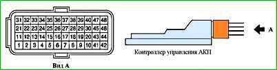
Assignment of contacts of the automatic transmission control controller (21126-1412020)
Contact - Circuit
- 1 - Exit. Solenoid valve on/off (switching)
- 2 - Entrance. Mode “1” of the automatic transmission range (mode) switch
- 3 - Login. Mode “2” of the automatic transmission range (mode) switch
- 4 - Login. Mode “D” of the automatic transmission range (mode) switch
- 5 - Login. Mode “N” of the automatic transmission range (mode) switch
- 6 - Entrance. Mode “R” of the automatic transmission range (mode) switch
- 7 - Login. Mode “P” of the automatic transmission range (mode) switch
- 8 – 10 - Not used
- 11 - Weight of input devices
- 12 - Entrance. Transmission fluid (oil) temperature sensor
- 13 – 20 - Not used
- 21 - Exit. ROM resolution (EEPROM)
- 22 - Entrance. ROM data (EEPROM)
- 23 - CAN line
- 24 - Login. Secondary (output) shaft speed sensor (DSA)
- 25 - Not used
- 26 - Exit. Sensor power supply +5 V
- 27 – 29 - Not used
- 30 - Exit. Downshift clutch solenoid valve
- 31 - Exit. ROM synchronization (EEPROM)
- 32 - Not used
- 33 - CAN line
- 34 - Not used
- 35 - Entrance. Primary (input) shaft speed sensor
- 36 - Not used
- 37 - Exit. Electromagnetic line pressure control valve
- 38 - Exit. Torque converter lockup clutch solenoid valve
- 39 - Exit. Brake solenoid valve 2-4 gears
- 40 - Exit. Overdrive clutch/downshift/reverse brake solenoid valve
- 41 – 42 - Weight of power stages
- 43 – 44 - Not used
- 45 - Entrance. Terminal “30” + battery
- 46 - Not used
- 47 – 48 - Entrance. Ignition switch terminal 15
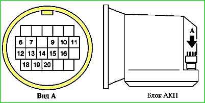
Assignment of contacts of the automatic transmission connector (21902-1700010)
Contact - Circuit
- 1 – 5 - Not used
- 6 - Downshift clutch solenoid valve
- 7 - Overdrive/downshift/reverse brake solenoid valve
- 8 - Not used
- 9 - ROM resolution (EEPROM)
- 10 - speed sensor of the primary (input) shaft
- 11 - transmission fluid (oil) temperature sensor
- 12 - 2nd-4th gear brake solenoid valve
- 13 - Solenoid valve for regulating pressure in the line
- 14 - Sensor power supply +5 V
- 15 - ROM synchronization (EEPROM)
- 16 - Weight of sensors
- 17 - Not used
- 18 - Torque converter lockup clutch solenoid valve
- 19 - Solenoid valve on/off (switching)
- 20 - ROM data (EEPROM)
- 21 – 22 - Not used
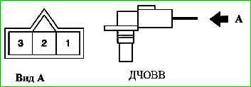
Assignment of contacts of the DCHOVV connector (21902-3843010)
Contact - circuit:
- 1 - sensor mass;
- 2 - sensor signal;
- 3 - sensor power supply
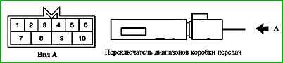
Assignment of contacts of the gearbox range (mode) switch connector
Contact - Circuit
- 1 - Not used
- 2 - Mode “2” of the automatic transmission range (mode) switch
- 3 - Mode “1” of the automatic transmission range (mode) switch
- 4 - Mode “D” of the automatic transmission range (mode) switch
- 5 - Mode “R” of the automatic transmission range (mode) switch
- 6 - Food. Terminal "15" ignition switch
- 7 - Starter (+)
- 8 - Mode “N” of the automatic transmission range (mode) switch
- 9 - Mode “P” of the automatic transmission range (mode) switch
- 10 - Starter (-)
List of automatic transmission controller fault codes 21126-1412020-00
Automatic transmission controller fault codes
Code - Description
- P062F - Controller, error reading - writing EEPROM
- P0705 - automatic transmission mode switch position sensor, circuit faulty
- P0706 - Automatic transmission mode switch position sensor circuit, signal out of acceptable range
- P0711 - Transmission fluid temperature sensor circuit, signal out of range
- P0712 - Transmission Fluid Temperature Sensor Circuit Low Signal
- P0713 - Transmission fluid temperature sensor circuit high signal
- P0717 - Input shaft speed sensor circuit, no signal
- P0720 - output shaft speed sensor, circuit faulty
- P0731 - Gear 1, incorrect gear ratio
- P0732 - Gear 2, incorrect gear ratio
- P0733 - Gear 3, incorrect gear ratio
- P0734 - Gear 4, incorrect gear ratio
- P0740 - Torque converter lock-up clutch, circuit faulty
- P0743 - Torque converter lock-up clutch, circuit faulty
- P0744 - Torque converter lock-up clutch, circuit signal intermittent
- P0863 - Automatic transmission controller, communication circuit faulty
- P0962 - Pressure control solenoid, control circuit short to ground
- P0963 - Pressure control solenoid, control circuit shorted to on-board power
- P0973 - Switching solenoid, control circuit short to ground
- P0974 - Switching solenoid, control circuit shorted to on-board power
- P1701 - Power circuit is faulty
- P1735 - Gear 1 blocked
- P1736 - Transmission 2 blocked
- P1737 - Gear 3 blocked
- P1738 - Gear 4 blocked
- P1744 - Torque converter lock-up clutch, unstable signal in the circuit
- P17AA - Downshift clutch solenoid, control circuit short to ground
- P17AB - Downshift clutch solenoid, circuit faulty
- P17AD - 2nd-4th gear brake solenoid, control circuit short to ground
- P17AE - 2nd-4th gear brake solenoid, circuit faulty
- P17BO - Overdrive/Downrange Brake/Reverse Clutch Solenoid, Control Circuit Short to Ground
- P17B1 - Overdrive/underdrive/reverse brake solenoid, circuit faulty
- U0073 - CAN bus disabled
- U0100 - CAN bus, no data from the COURT controller
- U0140 - CAN bus, no data from brake pedal switch
- U0155 - CAN bus, no data from instrument cluster
- U0300 - CAN bus, message parameters incompatibility
- U1000 - CAN bus, circuit faulty
If several fault codes are detected simultaneously, check the codes in accordance with the list of priorities.
List of priority fault codes
- Priority - Fault code
-1-
- P0863 Automatic transmission controller, communication circuit faulty
- U0073 CAN bus disabled
- U0100 CAN bus, no data from the COURT controller
- U0140 CAN bus, no data from brake pedal switch
- U0155 CAN bus, no data from instrument cluster
- U0300 CAN bus, message parameters incompatibility
- U1000 CAN bus, circuit faulty
- 2 -
- P0740 Torque converter lock-up clutch, circuit faulty
- P0743 Torque converter lock-up clutch, circuit faulty
- P0962 Pressure control solenoid, control circuit short to ground
- P0963 Pressure control solenoid, control circuit shorted to the on-board network
- P0973 Switching solenoid, control circuit short to ground
- P0974 Switching solenoid, control circuit shorted to the on-board network
- P17AA Downshift clutch solenoid, control circuit shorted to ground
- PI7AB Downshift clutch solenoid, circuit faulty
- P17AD Brake solenoid 2-4 gears, control circuit short to ground
- P17AE Brake solenoid 2-4 gears, circuit faulty
- P17BO Overdrive/underdrive/reverse brake solenoid, control circuit short to ground
- P17B1 Overdrive/downshift and reverse clutch solenoid, circuit faulty
- 3 -
- P062F Controller, error reading - writing EEPROM
- P0705 Automatic transmission mode switch position sensor, circuit faulty
- P0706 Automatic transmission mode switch position sensor circuit, signal output out of acceptable range
- P0711 Transmission fluid temperature sensor circuit, signal out of range
- P0712 Transmission fluid temperature sensor circuit, low signal
- P0713 Transmission fluid temperature sensor circuit, high signal level
- P0717 Input shaft speed sensor circuit, no signal
- P0720 Output shaft speed sensor, circuit faulty
- P1701 Power circuit is faulty

")
")
")
")
")