Engine cooling system - liquid, closed type, with forced circulation of coolant
The main elements of the system are the water pump, radiator, thermostats, fan, fan drive fluid coupling, fluid coupling switch, expansion tank, bypass pipes, blinds.
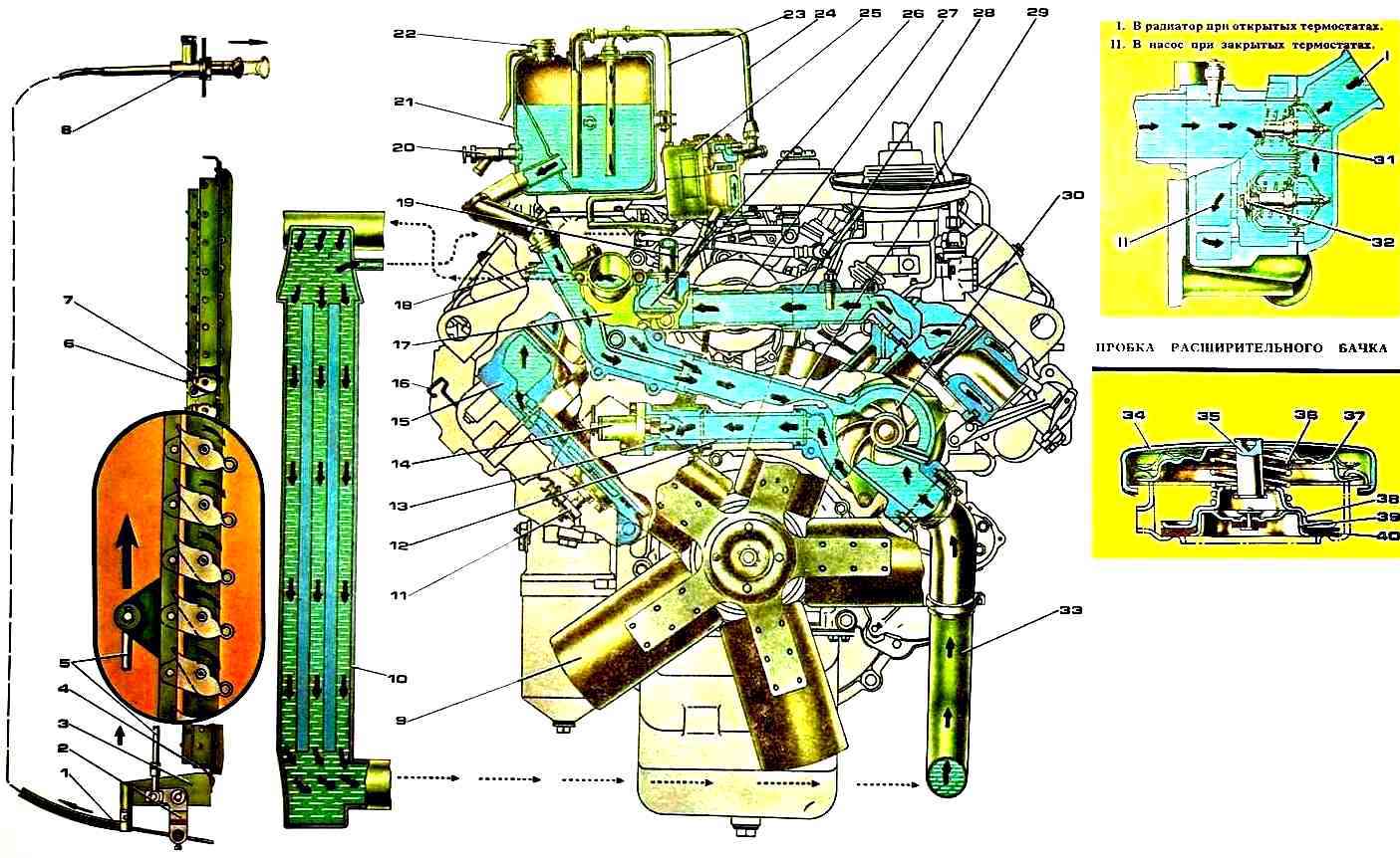
During engine operation, coolant circulation in the system is created by a centrifugal pump.
The liquid from the pump is pumped into the water cavity of the left row of cylinders, and through the pipe into the water cavity of the right row of cylinders.
Washing the outer surfaces of the cylinder liners, the coolant enters the water cavities of the cylinder heads through holes in the upper mating planes of the cylinder block.
From the cylinder heads, hot liquid flows through drainage pipes into the thermostat box, from which, depending on the temperature, it is directed to the radiator or to the inlet of the water pump.
The temperature of the coolant in the system is maintained within 80-98 °C.
Thermal conditions of the engine are ensured automatically by thermostats and a fan drive fluid coupling switch, which change the direction of fluid flow and the fan operating mode depending on the temperature of the coolant in the engine cooling system.
To speed up engine warm-up, as well as maintain engine temperature during the cold season, shutters are installed in front of the radiator.
Thermostats with solid filler and direct valve stroke, designed to automatically regulate the thermal conditions of the engine, are located in a box mounted on the front end of the right row of the cylinder block.
On a cold engine, the fluid inlet to the radiator is closed by a valve, and the inlet to the bypass pipe to the water pump is open by a valve.
Coolant circulates bypassing the radiator, which speeds up engine warm-up.
When the coolant temperature reaches 80 °C, the active mass - ceresin, enclosed in the cylinder, melts, increasing in volume. At the same time, the cylinder begins to move to the right, opening the valve and closing the valve.
Coolant begins to circulate through the radiator.
At a temperature range of 80-93°C, coolant continues to flow through the bypass pipe to the pump inlet and through the radiator, the valves are partially open.
At a temperature of 93°C, the valve opens completely, with all the liquid circulating through the radiator.
When the coolant temperature drops to 80 °C and below, the volume of ceresin decreases, and the valves, under the action of the thermostat springs, return to their original position.
The fan drive fluid coupling transmits torque from the crankshaft to the fan.
The front cover of the block and the bearing housing are connected with screws and form a cavity in which the fluid coupling is installed.
Radiator shutters are designed to regulate the flow of air pumped through the radiator grille.
They are made in the form of a set of horizontal plates made of galvanized iron, united by a common frame and equipped with a hinge device that ensures their simultaneous rotation around their axes. The louvers are attached to the radiator frame in front of the cooling grille.
Fan - axial type, five-blade, installed on the driven shaft wow.
The fan rotates in a diffuser mounted on the radiator frame, which reduces the suction of air from the sides by the blades and thereby increases the air flow drawn by the fan through the radiator.
The expansion tank is installed on the engine on the right side along the direction of the car and is connected to the thermostat box, the upper radiator tank and the compressor.
The expansion tank serves to compensate for changes in the volume of coolant when it expands due to heating, and also allows you to control the degree of filling of the cooling system and helps remove air and steam from it.
A steam-air plug with inlet (air) and outlet (steam) valves is installed in the neck of the expansion tank.
The exhaust valve, loaded with a spring, maintains excess pressure in the cooling system up to 56.9-78.5 kPa (0.58-0.80 kgf/cm 2), the intake valve, loaded more weak spring, prevents the creation of vacuum in the system when the engine cools down.
The inlet valve opens and communicates the cooling system with the atmosphere at a vacuum of 0.98-12.7 kPa (0.01-0.13 kgf/cm 2).
Coolant is poured into the engine through the neck of the expansion tank.
The liquid level in the expansion tank is controlled by a level control valve, which should be located above the control level valve, while the upper level of liquid in the tank should be ½-2/3 of the height of the tank.
Control of the coolant temperature in the system is carried out by a pointer on the instrument panel.
When the temperature in the cooling system increases to 98 °C, the indicator lamp for emergency overheating of the coolant lights up.

")
")
")
")
")