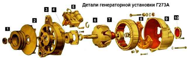
The generator serves as a source of electricity for the car when the engine is running. The main parts of the generator are the stator and the rotor
On the inside of the stator teeth there are 18 coils installed, made of insulated copper wire and connected in series, six pieces each, in three groups.
The groups are connected in a star circuit, three terminals from which go to the rectifier unit.
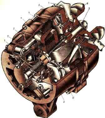
The rotor is a steel shaft, onto the corrugated surface of which two six-pointed steel magnetic cores are pressed.
Between them, an excitation winding made of insulated copper wire is installed on a steel sleeve.
On the rotor shaft there are two copper slip rings, isolated from the shaft and from each other. The ends of the excitation winding are soldered to them.
Copper-graphite brushes are pressed against the slip rings by springs.
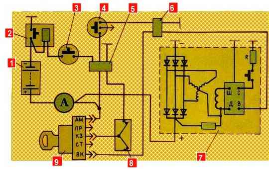
When the mass of the batteries and the instrument switch and starter are turned on in position “1” or “2”, the current from the battery passes through the brushes and slip rings into the field winding.
A magnetic flux is formed around the excitation winding screws, directed by the rotor magnetic cores.
When the rotor rotates, the magnetic flux that crosses the windings of the stator coils also rotates with it.
They generate alternating current (if the circuit is closed), which goes to the rectifier unit.
In this block it is converted into direct current, which goes to all consumers.
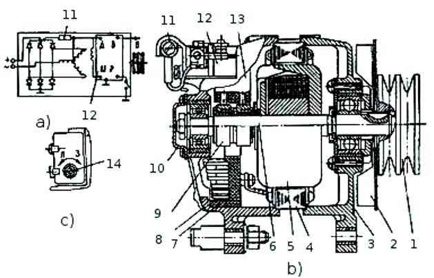
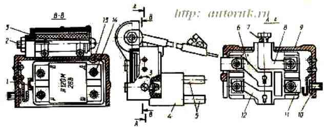
The brush holder of the generator set G 273V has a built-in small-sized voltage regulator Y120M, which is an integrated circuit. It serves to maintain the voltage generated by the generator within specified limits.
The regulator has four terminals.
With these terminals, the regulator is installed in the brush holder so that the terminals marked with the letters Ш, Д, В and Р lie on the conductive busbars.
The conductive terminal “B” of the voltage regulator is brought out and a wire is connected to it that powers the generator voltage regulation circuit.
The brush holder also contains a feed resistance, which serves to ensure reliable excitation of the generator at engine idle speed.
On the brush holder body there is a screw 10 for the seasonal voltage regulation. The screw has two positions: “L” - summer, “3” - winter.
When the screw is set to position “3”, the voltage maintained by the regulator is 1.5-3.0 V higher than with summer regulation, which is necessary to improve charging of batteries while increasing their internal resistance in winter conditions.</ p>
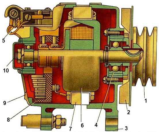
The G 288 alternating current generator with electromagnetic excitation is also a three-phase twenty-pole electrical machine with a built-in rectifier.
The generator has the following terminals: “+” - for connecting batteries and load, “—” - for connecting to vehicle ground, “Ш” - for connecting to the “VK” terminal of the instrument switch and starter and the “Ш” terminal voltage regulator.
The voltage regulator built into the generator brush holder is assembled using an integrated circuit and serves for automatic Safely maintain the generator voltage within the specified limits necessary to ensure the charging mode of the battery and the operation of consumers.
The voltage regulator has a seasonal adjustment switch (see Fig. 2).
The adjustable voltage level of the generator in switch position L (summer) should be within 27-28 V, in position 3 (winter) - 28.8-30.2 V.
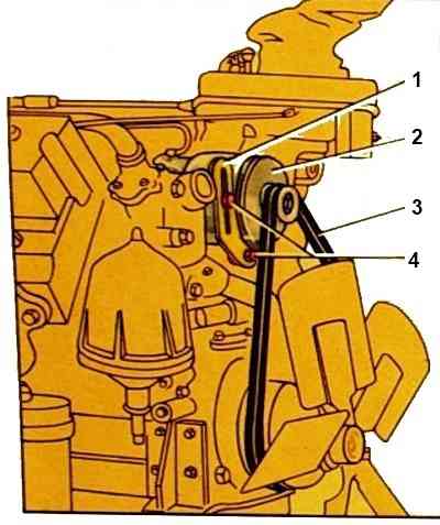
The generator is located in the upper front part of the engine and is attached with two legs to the bracket, and the third to the tension bar, and is driven by two V-belts.
The belts are tensioned by moving the generator. Generator drive ratio 2.41.
The generator has the following terminals:
- "+" - for connecting the battery and load;
- "-" - for connecting to the vehicle ground;
- B - for connection to the VC terminal of the instrument switch and starter;
- - plug on the housing for phase output.
G273A generator
The generator needs to be replaced:
- - when the shaft bearings are worn or destroyed;
- - breakage of covers in case of damage to the windings, as well as breakdown of the rectifier unit
Symptoms of malfunctions:
- - extraneous noise in the operation of the generator or shaft jamming;
- - lack of charging current when the engine is running at a crankshaft speed of more than 600 min -1 with a working voltage regulator, battery, generator circuits and normal drive belt tension
Removing the generator
Disconnecting the car batteries
Raise the cabin to the first position
Disconnect the plug block and electrical wires from the generator terminals
Unscrew the coupling bolt of the split support of the generator bracket 1-2 turns and loosen the stud nut
Unscrew the bolt securing the tension bar and loosen the bolt securing the tension bar to the generator
Turning the generator down, loosen the drive belts
We remove the belts from the pulley grooves and remove the generator by unscrewing the stud nut and unscrewing the coupling bolt
Installing a generator
Install the generator on the bracket, put a spring washer on the stud, tighten the nut by hand and screw in the coupling bolt
Installing drive belts in the pulley grooves
Screw in, without tightening, the tension bar mounting bolts
Move the generator up and tighten the belts
Tighten the bolts securing the tension bar, tighten the nut of the stud securing the generator to the bracket and the pinch bolt of the split support
A correctly tensioned belt, when pressed on the middle of the largest branch with a force of 39.2 N (4 kgf), should have a deflection of 15-22 mm
Connect the wires to the generator terminals and the plug block
Lowering the cabin
Batteries
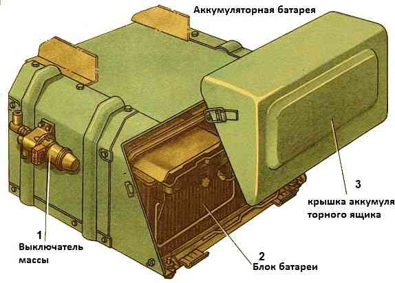
Lead-acid batteries with a voltage of 12 V and a capacity of 190 Ah.
Two batteries are connected in series and provide a voltage of 24 V.
Each battery consists of six batteries interconnected by intercell connections with copper inserts to reduce internal resistance.
The brand of KamAZ car batteries is 6ST-190T (6ST-190A).
Several factories produce such batteries. The manufacturer's trademark is applied to the intercell connection between the third and fourth batteries.
Replacing batteries
Batteries are removed for replacement and recharging or for repairs
Removing batteries
Disconnecting the car batteries
Open the latches securing the battery box cover and remove the cover
Loosen the nuts of the tie rods securing the battery clamping frames, remove the frame
Remove the battery covers
Unscrew the bolt securing the protective strips and remove the strips
Unscrew the nuts of the bolts securing the ends of the electrical wires to the battery terminals and disconnect the wires
Remove the batteries from the car (remove with an assistant)
Installing batteries
Installing batteries in the box
Connect the wire ends to the battery terminals and secure them with bolts and nuts
Batteries are connected to each other in series
We connect the negative terminal through the battery switch
Coat the terminals with VTV-1 grease
Install and secure protective strips
Installing the battery covers and securing them with clamping frames
Installing and securing the battery box cover
We turn on the batteries and check the operation of the batteries by starting the engine

")
")
")
")
")