The suspension is a set of guide devices and elastic elements connecting the wheels to the frame;
- serves to ensure the stability and smooth running of the car, as it softens the impacts perceived by the wheels from road unevenness, and is also designed to transmit all forces and moments acting between the wheels and the frame of the car.
The front suspension of KamAZ vehicles is leaf spring, dependent, in which the movement of one wheel caused by road unevenness is transferred to the other wheel; made on leaf springs.
The elastic element of the suspension is the spring.
It not only softens the shocks received by the car’s wheels from road unevenness, but also acts as a guiding device to the front axle, transmitting traction and braking forces from the wheels to the car’s frame.
The springs are assembled from curved steel sheets of different lengths (the higher the sheet is located, the longer it is).
The leaf that has the greatest length is called the root leaf.
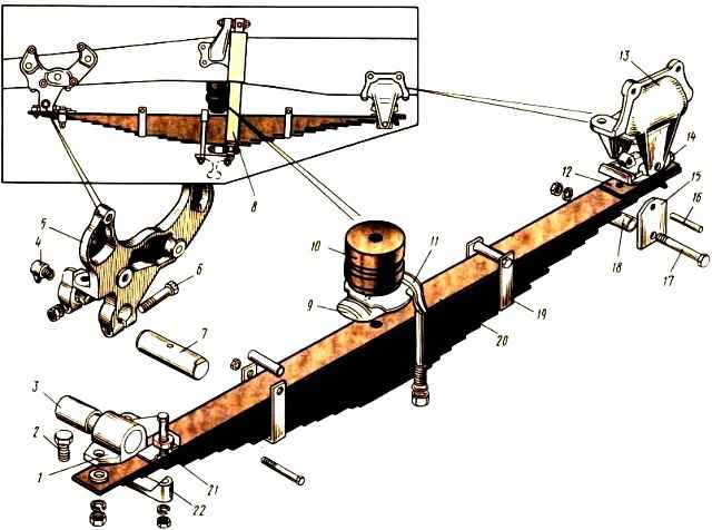
The front axle is suspended from the frame side members on two springs using brackets 5 and 13 (Fig. 1).
The front end of the spring is connected to the frame bracket 5 using eye 1 and pin 7.
The detachable eye 1 is attached to the main leaf of the spring with a bolt 2 and a plate 22, which is secured to the eye with two bolts 21. A bushing 3 is pressed into the eye.
Finger 7 connecting the eyelet to the bracket is fixed with two bolts 6.
Fingers are lubricated through grease fitting 4.
The rear end of the spring is sliding and, through the lining 12 riveted to the main sheet, rests on a replaceable block 14 located on the bracket.
To protect the walls of the bracket 13 from wear, liners 15 are installed on the fingers 16 of the crackers, tightened with a bolt 17 through a spacer sleeve 18.
The spring is made of 15 sheets.
The main leaf of the spring is rectangular in section, and the rest are T-shaped. This allows you to reduce the weight of the spring while maintaining its characteristics.
In the middle part of the spring there is a pad 9, through which the spring is attached to the front axle with two stepladders 11. The overlay has a stamping that fits into the recess of the first sheet.
Each leaf of the spring with its protrusion fits into the recess of the underlying leaf, and the protrusion of the last leaf fits into the corresponding recess of the shock absorber bracket 8, which is, in turn, fixed on the front axle beam.
The spring leaves are additionally held against lateral displacement by clamps 19.
An additional elastic element of the front suspension is a rubber buffer 10, bolted to the frame side member. It limits suspension travel and increases spring durability.
In the absence of a buffer, the durability of the spring is reduced by three times.
In the front suspension of off-road vehicles with a 6X6 wheel arrangement, two buffers are used for each spring.
To protect the walls of the bracket 13 from wear, there are nuts on the fingers 16 and liners 15 are installed, tightened with a bolt 17 through a spacer sleeve 18.
The spring is made of 15 sheets. The main leaf of the spring is rectangular in section, and the rest are T-shaped. This allows you to reduce the weight of the spring while maintaining its characteristics.
In the middle part of the spring there is a pad 9, through which the spring is attached to the front axle with two stepladders 11. The overlay has a stamping that fits into the recess of the first sheet.
Each leaf of the spring with its protrusion fits into the recess of the underlying leaf, and the protrusion of the last leaf fits into the corresponding recess of the shock absorber bracket 8, which is, in turn, fixed on the front axle beam.
The spring leaves are additionally held against lateral displacement by clamps 19.
An additional elastic element of the front suspension is a rubber buffer 10, bolted to the frame side member. It limits suspension travel and increases spring durability.
In the absence of a buffer, the durability of the spring is reduced by three times.
In the front suspension of off-road vehicles with a 6X6 wheel arrangement, two buffers are used for each spring.
The oscillations of the spring die out slowly, as they are damped by friction between its leaves.
To more quickly dampen vibrations and increase the durability of the springs, shock absorbers are installed in the front suspension.
The principle of action of shock absorbers is that, as a result of relative movements of the frame and unsprung parts of the car, liquid is distilled from one cavity of the shock absorber to another through small flow sections, absorbing the energy of oscillatory movements.
Shock absorbers are filled with a special liquid, the viscosity of which varies little depending on the ambient temperature.
The oscillatory motion of the frame can be represented as consisting of two movements: the compression stroke of the spring, when the frame and the bridge move closer together, and the rebound stroke, when the frame and the bridge diverge.
The double-acting shock absorber absorbs vibration energy during both rebound and compression.
The resistance created by the shock absorber during compression is approximately three times less than the resistance during rebound, since the shock absorber must dampen mainly free vibrations of the suspension during the rebound stroke and not increase the stiffness of the springs.
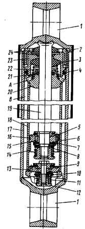
Shock absorber: 1 - eye; 2- tank nut; 3 - rod seal; 4 - reservoir nut seal; 5 - bypass valve; 6 - hole in the outer row; 7 - recoil valve; 8,11, 22 - springs; 9 - compression bypass valve; 10 - compression valve; 12 - nut; 13 - bypass valve holes; 14 - piston; 15 - hole in the inner row; 16 - piston ring; 17 - tank body; 18 - working cylinder; 19 - piston rod; 20 - rod guide; 21 - guide oil seal; 23 - seal ring; 24 - rod seals; A - hole for draining liquid into the tank; B - tank cavity
Piston 14, fixed to rod 19 with a nut, moves in working cylinder 18 filled with shock-absorbing fluid.
The piston has two rows of through holes, evenly spaced along two circles with different diameters.
The holes located along the larger circumference are closed from above by a bypass valve plate 5, pressed by a conical spring.
The holes located on the smaller circle are blocked from below by the discs of the rebound valve 7, pressed by a cylindrical spring 8.
The rod 19 moves in the guide 20. The rod is sealed with an oil seal 21, a rubber oil seal 3, and felt oil seals 24.
Oil seal 3 is placed in a housing (holder) 23 and is pressed through a washer by a conical spring 22. Felt seals are installed to protect oil seal 3 from dirt and dust.
To facilitate the operation of the oil seal 3 and increase its reliability, there are holes “A” in the guide, through which the liquid that has leaked through the gap between the rod and the guide is drained into the reservoir, as a result of which the liquid pressure on the oil seal is reduced.
The reservoir is sealed with an oil seal 4, and the surface of the rod as it exits the cylinder is protected from damage by a casing.
The rod seal and the body are tightened with nut 2 of the tank.
At the bottom of the cylinder there is a compression valve, consisting of a housing, a disc bypass valve 9, pressed by a conical spring, and compression disk valves 10, pressed by a cylindrical spring.
The valve body has 13 holes located in circles with different diameters.
The shock absorber exhibits the greatest resistance during stretching (rebound stroke), when the sprung part of the car moves away from its unsprung part.
When stretched, the fluid above the shock absorber piston experiences compression.
The bypass valve 5 closes, and the liquid flows through the internal holes 15 in the piston to the rebound valve 7.
Due to the force of the coil spring, a certain resistance of the shock absorber is created.
At the same time, the bypass valve 9 is open and freely passes through the holes 13 from the cavity of the reservoir into the cavity of the working cylinder a part of the liquid equal to the volume of that part of the rod 19 that is currently being removed from the working cylinder.
When the spring is compressed, the shock absorber piston moves down, the bypass valve 5 opens and the liquid flows freely through the outer row of holes 6 into the space above the piston.
In this case, liquid in a volume equal to the inserted part of the rod is forced into the reservoir through the internal holes in the housing, having previously overcome the resistance of the spring 11 of the compression valve 10.
The bypass valve 9 is closed under liquid pressure, and the force of the spring 11 creates the necessary resistance for the flow of liquid during the compression stroke.
When the car moves on a road with small obstacles, the amplitude of the suspension vibrations is insignificant, and the resistance created by the shock absorber is small.
In this case, the liquid flows through calibrated holes in the throttle discs of the rebound and compression valves.
On a rough road, the amplitude of suspension vibrations increases, and the shock absorber must provide more resistance to prevent the car from rocking.
Due to an increase in the piston speed, the fluid pressure increases and, consequently, the force developed by the shock absorber.
Both during smooth and sharp compression and rebound strokes, the impact energy is absorbed by the shock absorber, which leads to rapid damping of suspension vibrations.
The front suspension of KamAZ-53212 vehicles also has an anti-roll bar, which increases the angular rigidity of the suspension, reducing the roll angle of the sprung part of the vehicle, and increases the stability of the vehicle when driving.
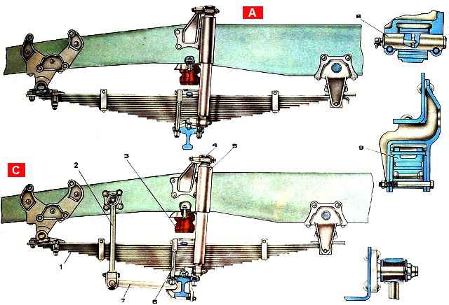
Rod 7 (Fig. 3.) of the stabilizer in the middle part is fixed to the front axle beam in rubber bearings using clips, pads and stepladders.
The rod is pivotally connected by 2 posts to brackets mounted on the frame side members. The racks are also pivotally connected to the frame brackets.
When the wheels simultaneously lift and hit an uneven road, the bar rotates freely in the holders and the stabilizer does not work.
When the car frame rolls sideways, the racks move relative to each other in the vertical plane and the rod, twisting, prevents the frame from tilting relative to the road.

")
")
")
")
")