Clutch drive of KamAZ vehicle
Clutch drive is remote, hydraulic with pneumatic booster.
The pneumatic booster makes it much easier for the driver to disengage and hold the clutch in the disengaged state.
The drive consists of clutch pedal 1 (Fig. 1) with release spring 11, master cylinder 2, pneumatic booster 18, tubes 6 and hoses for supplying working fluid from the master cylinder to the clutch booster, tube 13 for supplying compressed air from the brake pneumatic drive to to the clutch booster, as well as from tank 5, which provides control over the fluid level.
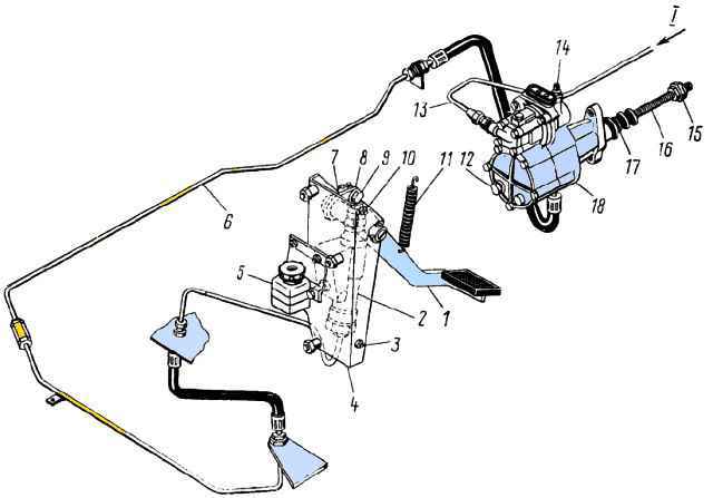
Clutch mechanism drive: 1 - pedal; 2 - main cylinder; 3, 10 - lower and upper stops; 4 - bracket; 5 - compensation tank; 6 – hydraulic pipeline; 7 - lever; 8 - piston pusher; 9 - eccentric finger; 11 - tension spring; 12 - plug; 13 - pipeline; 14 - air release valve; 15 - spherical adjusting nut; 16 – pneumatic hydraulic booster piston pusher; 17 - protective cover; 18 - pneumatic hydraulic booster; I - compressed air
When the clutch is disengaged, the force of the driver's foot is transmitted through the pedal, lever and rod to the main cylinder 2 (Fig. 1), from where liquid under pressure through pipelines 10 enters the housing of the follower device 4, which at the same time provides the supply of compressed air supplied through air line 5 to pneumatic booster cylinder 3.
At the same time, fluid under pressure enters from the main cylinder into the working hydraulic cylinder 6 of the amplifier.
The follower device, the pneumatic booster cylinder and the working hydraulic cylinder are made in one unit - the pneumohydraulic booster.
The total force, determined by the air pressure in the pneumatic booster cylinder and the fluid pressure in the working cylinder, is transmitted to the rod 9 and through the lever 8, shaft and release sleeve ensures the movement of the clutch with bearing 7 necessary to disengage the clutch.
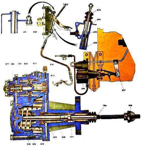
A more expanded diagram is shown in Figure 2.
Clutch drive maintenance
At service 2:
- - tighten the bolts securing the pneumatic clutch drive booster:
- - check by external inspection the tightness of the clutch drive, if necessary, eliminate the leak and bleed the drive hydraulic system;
- - check the action of the release springs of the clutch pedal and the clutch release fork shaft lever, correct the faults if necessary;
- - adjust the clutch drive;
- - lubricate the clutch release clutch bearing and the clutch release fork shaft bushing;
- - check the fluid level in the clutch compensation tank and add if necessary;
- - drain the condensate from the air-hydraulic booster by unscrewing plug 12 (see Fig. 1).
Adjusting the clutch drive consists of checking and adjusting the free play of the clutch pedal, the free play of the clutch release clutch and the full travel of the pneumatic hydraulic booster pusher.
Checking the free play of the clutch release clutch is carried out by manually moving the fork shaft lever from the adjusting spherical nut 15 of the pusher 16 of the pneumatic hydraulic booster of the clutch drive (in this case, it is necessary to disconnect the spring from the lever).
If the free play of the lever, measured at a radius of 90 mm, is less than 3 mm, then adjust it with the spherical nut of the pneumatic hydraulic booster pusher to a value of 3.7-4.6 mm, which corresponds to a free play of the clutch release of 3.2-4 mm .
Then check the full stroke of the pusher of the pneumatic hydraulic booster by pressing the clutch pedal all the way, while the full stroke of the pusher must be at least 25 mm; with a smaller stroke, complete disengagement of the clutch is not ensured.
If the pusher stroke of the pneumatic hydraulic booster is insufficient, check the free play of the clutch pedal, the amount of fluid in the master cylinder and clutch reservoir, and, if necessary, bleed the clutch hydraulic system.
Pedal free play, rel corresponding to the start of operation of the master cylinder, should be 6-12 mm.
It should be measured in the middle part of the clutch pedal area.
If the free play is outside the limits specified above, adjust the gap “A” between the piston and the master cylinder piston pusher.
Adjust the gap between the piston and the master cylinder piston pusher using eccentric pin 9 (see Fig. 1), which connects the upper eye of the pusher 8 to the pedal lever 7.
Adjust the gap when the tension spring presses the clutch pedal against the upper stop 10.
Turn the eccentric pin so that the pedal moves from the top stop until the pusher touches the piston by 6-12 mm, then tighten and cotter the castle nut.
Lubricating the clutch
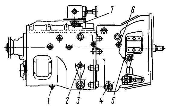
Lubrication points: 1 - drain plug; 2 - filler plug with oil level indicator; 3, 4 - drain plugs with a magnet; 5 - support grease fitting; 6 - release bearing grease nipple; 7 - breather
Lubricate the clutch release fork shaft bushings through two grease nipples 5, and the clutch release clutch bearing through grease nipple 6, making no more than three strokes with a syringe. Otherwise, excess lubricant may get into the clutch housing.
Control the Neva fluid level in the compensation tank of the main cylinder visually.
The normal liquid level in the tank corresponds to 15-20 mm from the top edge of the tank. The total fluid volume in the clutch hydraulic drive is 380 cm 3.
During service “C” (autumn), change the fluid in the clutch hydraulic system.
Repair
Perform bleeding of the clutch drive hydraulic system after eliminating leaks in the hydraulic drive in the following order:
- Clean the rubber protective cap of the air release valve 14 (see Fig. 1) from dust and dirt, remove it and put the rubber hose supplied with the car onto the valve head. Dip the free end of the hose into Neva brake fluid poured into a clean glass container.
- Press the clutch pedal sharply 3-4 times, and then, keeping the pedal pressed, unscrew the air release valve ¼-1/3 turn.
Under the influence of pressure, part of the liquid and the air contained in it in the form of bubbles will come out through the hose.
- When the liquid stops coming out, close the air release valve.
- Repeat operations according to paragraphs. 2 and 3 until the release of air from the hose completely stops.
During the bleeding process, it is necessary to add brake fluid to the system, not allowing its level in the compensation tank of the master cylinder to decrease by more than 2/3 of normal in order to avoid atmospheric air entering the system.
After completing the bleeding, with the clutch pedal pressed, screw the air release valve all the way and only then remove the hose from its head and put on the protective cap.
Next, set the normal fluid level in the master cylinder.
Brake fluid that is released from the hydraulic system during bleeding can be used again after settling and subsequent filtration.
The quality of pumping is determined by the full stroke of the pneumatic hydraulic booster pusher.
Check for condensation in the power cylinder of the air-hydraulic booster.
To drain the condensate, unscrew the plug in the aluminum housing of the air-hydraulic booster.
To drain completely, lightly press the clutch pedal.
At least once every three years, it is recommended to flush the clutch drive hydraulic system with technical alcohol or clean brake fluid, disassemble the master cylinder and pneumatic power steering and refill with fresh brake fluid.
Wash the hydraulic system pipelines with alcohol or brake fluid and blow them with compressed air, having first disconnected both ends.
Before assembling, moisten the pistons and cuffs of the hydraulic system with brake fluid.
Replace defective (hardened, damaged working edges and worn) cuffs and protective covers.
When replacing the pneumatic hydraulic booster, replace the covers.
When replacing the pneumatic hydraulic booster for the clutch drive, to remove the pneumatic hydraulic booster:
- - release air from circuit IV of the auxiliary brake system drive and other consumers through the valve on the receiver;
- - remove the release spring of the clutch release fork shaft lever, disconnect the power steering air line, hydraulic hose and drain the fluid from the hydraulic drive system;
- - unscrew the two bolts securing the pneumatic hydraulic booster and remove the booster with the rod.
To install the pneumatic hydraulic booster: align the mounting holes with the holes in the clutch housing and secure the booster with two bolts with a spring and washers; connect the hydraulic hose of the pneumatic power steering and the air pipeline: install the release spring of the clutch release fork shaft. Pour brake fluid into the master cylinder compensation tank and bleed the hydraulic drive system.
Check the tightness of the pipeline connections (leaking of brake fluid from the connections is not allowed), if necessary, eliminate the leakage by tightening or replacing individual elements of the connections.
Check and, if necessary, adjust the gap between the end of the cover and the travel limiter of the gear divider valve rod.
When removing the clutch from the engine after disconnecting the gearbox, first screw four M10x1.25x62 coupling bolts into the pressure plate until it stops in the casing, and then unscrew the bolts securing the clutch casing to the flywheel and remove the casing with the pressure plate assembly, the middle and driven discs clutch.
If individual parts of the clutch are replaced, check the position of the thrust ring of the release levers before installing it on the engine.
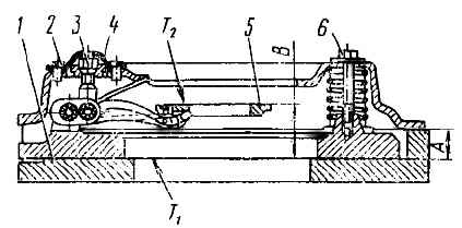
To check, install and secure the pressure plate assembly on a control stand (Fig. 4) or on a flywheel with an insert, ensuring the installation dimension “A” = (29+0.1) mm, and loosen the tightening bolts.
The correct position of the thrust ring is determined by the mounting dimension “B” = (54+0.3) mm, the runout of the end T2 relative to T1 should be no more than 0.2 mm.
If the position of the thrust ring is violated, adjust the position of the ring on the device using nuts 3, restoring dimension “B”, while the supporting surfaces of all four pull-off levers must simultaneously touch the thrust ring.
Do not adjust the position of the thrust ring using the specified nuts on the engine.
Before installing the clutch on the engine, place 15 g of lubricant 158 into the cavity of the front drive shaft bearing located in the crankshaft.
Install the clutch using a splined mandrel that ensures the axes of the driven disks are aligned with the axis of the crankshaft.
Pay attention to the correct relative position of the hubs of the driven disks - with short protruding ends towards each other.
The middle drive disk assembly should move easily in the flywheel slots under the action of the pull-out levers.
Install the pressure plate with housing assembly onto the engine flywheel also without additional adjustment, but without distortions, achieving this by uniformly tightening the mounting bolts with a torque of 54-61.8 Nm (5.5-6.3 kgcm).
After the bolts securing the casing to the flywheel are tightened, remove the tightening bolts from the pressure plate.
The runout of the thrust ring of the retraction levers relative to the axis of the crankshaft should be no more than 0.5 mm.

")
")
")
")
")