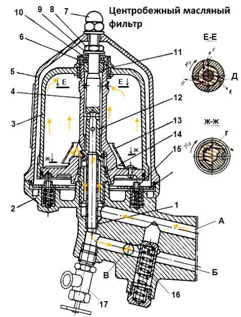
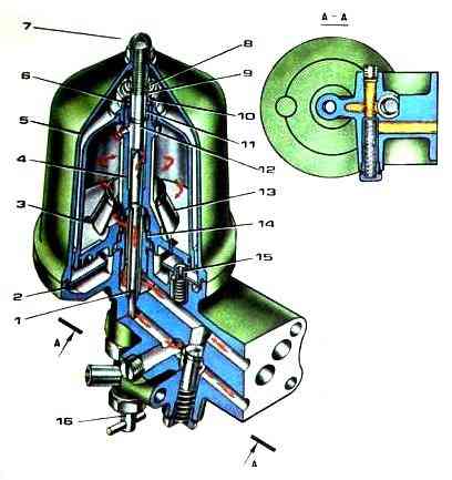
The centrifugal oil filter (Fig. 1) is bolted to the front crankcase cover on the right through a gasket so that the inlet “A” and outlet “B” to “C” channels are aligned with the corresponding channels in the cover
Rotor 4 rotates on axis 12, closed by cap 3, which is pulled to the rotor body by nut 6.
In order not to disturb the balancing of the rotor during assembly, it is necessary to align the marks on the rotor body and the outer side of the cap.
Together with the rotor, the oil in it rotates.
Suspended mechanical impurities under the influence of centrifugal forces are thrown away from the axis of rotation and deposited in a dense layer on the inner walls of the rotor.
The rotor drive method is active-reactive based on the nature of its rotating forces.
Rotation is imparted to the rotor as follows.
Oil pumped by the radiator section of the oil pump into the annular channel of axle 12 passes through channels "G".
Emerging at high speed from these channels directed tangentially to the circle, the oil flow acquires a rotational motion and, acting on the inner surface of the rotor, drags it into rotation.
This principle of energy transfer to the rotor flow is called active. Torque Ma is the active torque.
Oil deflector 13 deflects the oil flow downward and prevents the erosion of deposits in the rotor, especially during its acceleration, with a stream of oil emerging from channels "G" at a speed of more than 25 m/s.
Having passed under the screen, the oil moves upward, undergoing centrifugal cleaning along the way, and then is pumped into channels “D” (also located tangentially to the circle), from which it is thrown out at high speed into the internal annular channel of the rotor column.
The direction of this flow is opposite to the movement of oil in the channels G, therefore the reactive forces arising here create a reactive torque Мр, which coincides in direction with the active one.
These moments, added up, give a total torque Mk, under the influence of which the rotor rotates at a frequency of about 5000 rpm.
The rotor speed, and therefore the intensity of cleaning, depends on the pressure and temperature of the oil, as well as on the friction in the bearings.
Reducing friction is achieved by the fact that the rotor shifts upward during operation and rotates against bearing 10.
The lifting of the rotor is limited by thrust washer 9 within the gap.
Next, the oil enters the internal channel of the rotor axis 12 and through tube 1 into the channel of the centrifuge housing, from where, when the tap is open, it is supplied to the radiator or, bypassing it, through the drain valve into the pan if the tap is closed.
In addition to the drain valve, the filter housing contains a bypass valve 16. Both valves are adjusted by selecting shims.
You should know the main differences in the operation of an active-reactive centrifuge from a reactive one.
If in a reactive centrifuge the oil rotates the rotor, draining from it through nozzles, then in an active-reactive centrifuge there are no nozzles, so the oil is not saturated with air and is less oxidized.
It is impossible to determine the performance of an active-reactive centrifuge by the characteristic noise that is heard in jet centrifuges for 1.5-2 minutes after stopping the engine, since the rotor of an active-reactive centrifuge does not rotate at this moment.
Its performance is determined by the amount of deposits on the walls of the rotor cap.
During operation between TO-2, about 200 g of deposits should accumulate in the cap, their thickness is approximately 10 mm.
To wash the centrifugal filter rotor:
- - unscrew the nut of the filter cap and remove the cap;
- - turn the rotor around the axis so that the locking pins fit into the rotor hole;
- - unscrew the nut securing the rotor cap and remove eat it;
- - check the tightness of the rotor mounting nut on the axle, if necessary, tighten it with a torque of 78.5-88.3 Nm (8-9 kgf.m). Do not remove the rotor when servicing;
- - remove sediment from the caps and wash them with diesel fuel;
- - assemble the filter by aligning the marks on the cap and rotor.
Before installing the outer cap, release the pins of the locking device and check the rotation of the rotor on the axis; the rotor should rotate easily, without jamming. Tighten the cap nuts to a torque of 19.6-29.4 N.m (2-3 kgf.m).

")
")
")
")
")