The car is equipped with an electric windshield wiper with two blades.
The electric windshield wiper motor with gearbox and drive lever system is located in the engine compartment
The windshield wiper consists of an electric motor with a gearbox, a base, a lever system, brushes, a bimetallic fuse and a limit switch.
The gearbox worm is made as a single unit with the electric motor shaft. In mesh with the worm there is a worm wheel, the axis of which is connected to a lever system of drive and brushes.
The windshield wiper and washer are controlled by a switch located on the steering column.
After turning off the switch, the electric motor does not turn off immediately and the brushes continue to move along the glass until they reach the bottom position.
At this moment, the limit switch will switch the circuit and the electric motor will stop.
Technical characteristics of the windshield wiper
Window wiper 60.5205010 or 70.5205
Rated voltage 12 Volts
Number of double strokes per minute: at low speed, no more than 20-45
at high speed, at least 45
The difference between the first and second speed of double strokes per minute is at least 15
The force of pressing the brushes to the glass, N (kgf) 6.0—7.0 (0.6—0.7)
Sweep angle of brushes on wet glass, degrees: left - 85 right - 90
Current consumption, no more than 4 A
Relay for intermittent wiper operation 524.3747—01
Wiper maintenance
Periodically lubricate the hinge joints of the windshield wiper rods.
Lubrication should be done with motor oil, 5 drops at each connection point.
To obtain a good cleaning of the windshield, it is necessary to constantly monitor the condition of the glass surface, avoiding oil stains on it that interfere with the removal of moisture.
The rubber band of the brushes must be protected from oil and gasoline.
To avoid damage to the windshield, remember:
- - if there is dry dust and dirt on the glass, you cannot turn on the windshield wiper;
- - if it is necessary to remove the windshield wiper blades, it is recommended to put pieces of rubber tube on the ends of the arms.
The rubber band of the brush must be elastic, straight and free of flaws along the entire length adjacent to the glass edge.
Under these conditions, the brush should wipe heavily wetted glass in no more than five double strokes at low speed.
If necessary, install brushes as follows:
- - remove the brush levers from the axes;
- - turn on the windshield wiper and turn it off after 1-2 minutes;
- - install levers with brushes. The brushes should be positioned along the bottom plastic lining of the glass, but not touching it. Secure the levers in this position;
- - turn on the windshield wiper. When working, the brushes should not touch the cladding.
If the brushes hit the facing or stop too high after switching off, then it is necessary to slightly change the installation of the levers on the axle.
If the windshield wiper fails, it is necessary to determine whether the windshield wiper or the switch is faulty.
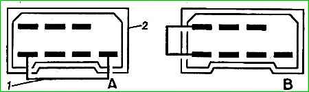
To do this, you need to disconnect the plug block from the switch (it is located under the instrument panel) and connect the plug tips of the block (which remains on the wiring harness going to the wiper), as shown in Fig. 1., "A" for low speed and fig. 1, "B" for high speed.
If the windshield wiper starts to operate, this indicates a faulty switch, and if not, the windshield wiper is faulty.
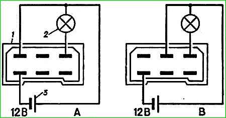
To check the functionality of the windshield wiper removed from the car, it is necessary to connect the windshield wiper connector according to the diagram shown in Fig. 2. (lamp 2 will flash).
If the wiper operates at low and high speeds, but does not work in intermittent mode, check the serviceability of the intermittent operation relay.
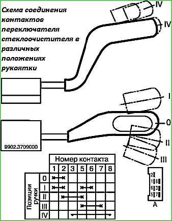
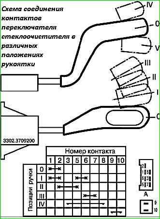
To check the switches using a test lamp, use fig. 3 and 4.
Wiper relay
To create intermittent wiper operation, an electronic wiper relay 524.3747 is used.
When the windshield wiper is turned on in intermittent mode, it should make 7-19 cycles per minute.
The serviceability of the relay can only be checked when working with the windshield wiper. A faulty relay must be replaced.
Window washer
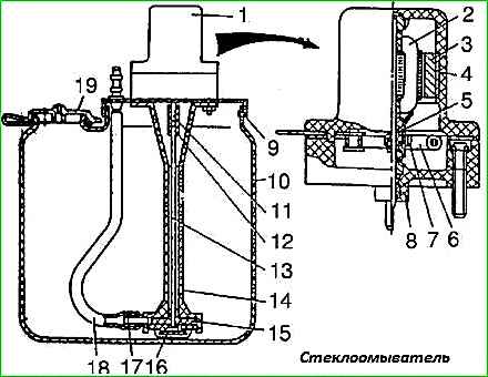
The windshield washer consists of a tank in which a pump driven by an electric motor, jets and hoses is installed (Fig. 5).
Water is used as a working fluid, and at temperatures below 0°C - Obzor liquid, produced in three brands:
- A - for ambient temperature up to minus 35°C,
- B - for ambient temperatures down to minus 20°C,
- B - for ambient temperatures down to minus 5°C.
Maintenance
Maintenance of the windshield washer consists of periodically checking the tightness of the hoses at the points of their connection to the tips and nozzles, washing the nozzles and suction filter, washing the reservoir and filling it with clean liquid.
The direction of water jets from the jets can be adjusted by turning the jet balls.

")
")
")
")
")