Replacement of pump and coarse filter GAZ-2705 with engine ZMZ-405, ZMZ-406
The pump is usually replaced when extraneous noise appears in the pump area, as well as when the engine fails and reduces power.
You must first check the pressure in the fuel supply system in the following order:
- - check the serviceability of the pressure regulator.
- - check the fuel pressure at idle. If the pressure is less than 300 kPa (3 kgf/cm 2), remove the pump and wash the fuel coarse filter mesh;
- - if this does not help, replace the fine fuel filter (see the article - “How to replace the fuel filter of a Gazelle car”)
Reduce the fuel pressure in the fuel supply system. To do this, remove the fuel pump fuse from the fuse block.
Start the engine and let it run until the fuel is completely exhausted from the fuel line. After this, the engine will stall.
Disconnect the negative terminal from the battery
For all-metal cars, remove the floor mat above the hatch

Remove the six screws securing the hatch cover at the base of the body above the fuel pump module

Remove the cover

Press the latch

Disconnect the wiring harness block from the fuel pump module

Press the latch

Disconnect the ends of the high pressure fuel line and the fuel drain line from the module fittings

Remove the eight screws securing the fuel pump module retaining ring

Remove the ring

We lift the module, tilting it to the side, remove it by removing the fuel level sensor float from the hole in the fuel tank, and drain the fuel from it into a previously prepared container.

Remove the rubber sealing ring from the tank flange.
A heavily compressed, hardened or torn ring must be replaced
Replacing the fuel coarse filter
Remove the fuel pump module

Remove the screw securing the fuel pre-cleaning grid

Removing the mesh

Disconnect the drain tube from the pump module body by prying it up with a screwdriver

Overcoming the force of the spring, we slightly move the module body up along the guides and, using a screwdriver, pry it off and remove the locking ring from one of the guides. After this, the module body can be moved slightly downwards from the bracket.

Press out the plastic clips

Remove the module housing from the bracket guides

To replace the fuel filter, pry up its base with a pointed tool

Remove the filter from the pump body, overcoming the resistance of the spring lock washer.

Before installing the filter, remove the lock washer

Straighten it with pliers and install it in the filter housing

Install the filter in reverse order
Install the module in the reverse order of removal.
When installing the fuel module into the fuel tank, the installation arrow on the module bracket must be directed towards the front of the vehicle.
When connecting fuel lines, follow the arrows on the fittings indicating the direction of fuel supply.
Technical characteristics of the submersible electric fuel pump module
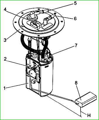
Module of submersible electric fuel pump 155.1139002: 1 – anti-drip cup; 2 - fuel level sensor; 3 - pressure ring; 4 - connector block for connection; 5,6 - tips; 7 - electric fuel pump; 8 - fuel level sensor float
Technical characteristics:
Type 155.1139002*
Rated voltage, V 12
Current consumption:
- when working in the system, no more than A 7.5
Performance at supply voltage, not less, l/hour:
- - 13.5 V 110
- - 10.8 V 80
Nominal operating pressure in the vehicle fuel system, kPa, 400
Maximum pressure, kPa 550-850
Working fluid – all brands of commercial gasoline in accordance with the operating manual
- working fluid temperature from minus 45°C to plus 65°C
95% module operating life:
- engine hours 5000
* - Submersible module 515.1139000-10, 9P2.960.031, 7D5.883.029, EO4.4100000-21 can be installed on some vehicles
When the reserve fuel balance in the gas tank is reached (less than 10 liters, rheostat resistance 230±10 Ohms), the signal lamp for reserve fuel balance turns on in the instrument cluster.
The module's electric fuel pump and fuel level sensor are non-removable ntable and maintenance-free products.
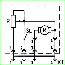
Schematic electrical diagram of the submersible electric fuel pump module 155.1139002: M – electric pump; R – fuel level sensor rheostat; SL – warning light switch
The circuit diagram of the module is shown in the figure
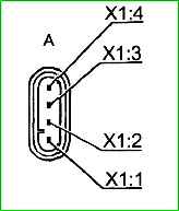
The location of the X1 connector contacts is shown in the figure

")
")
")
")
")